3D Scan, Section Study & Insights on Vehicles

BiW Benchmarking – Loadpath, RM, Sections, Cost, Philosophy
Alternator Generator detailed teardown & feature mapping
*All data/graphs/trends/images presented on this page are dummy/heavily masked/edited to remove specific details. They are intended only to showcase sample outcomes of such activities.
This Blog focuses on the structure and equipment of conventional alternators based on the detailed teardown study of Alternator Generator typically for three purposes:
- Disassembly and feature study of alternator
- Experience and knowledge for an individual’s personal database.
- New product development benchmarking.
Engineering insights are generated for study or packaging, integration, features, interface with other subsystems and more.
Alternator in Automobiles
An Alternator is a type of electrical Generator (AC generator) and it works on the principle of converting mechanical energy into electrical energy.
Types of Alternators
1. According to Design
- Salient Pole
- Cylindrical Rotor
2. According to Working Principle
- Revolving Armature
- Revolving Field
Alternator Chosen for Activity
The Alternator we have chosen for the activity is a conventional automotive DC Output alternator with dual asymmetrical internal fan and a split casing exposed stator core design.
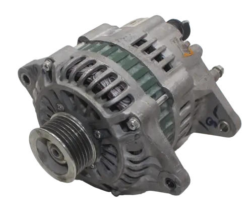
In the Alternator Generator, the all four main components of an alternator I.e., The Rotor, The Stator, The Regulator and The Rectifier will be analyzed for the activity. This blog will focus on our findings on Alternator Generator in the following areas:
- Alternator Generator architecture
- Feature mapping.
- Sub assembly level teardown.
- Stator & Rotor assembly.
- Alternator casing & other structural components.
- xcPEP’ s role in analysis.
Architecture mapping
In the architecture module of xcPEP, the following are mapped:
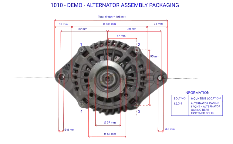
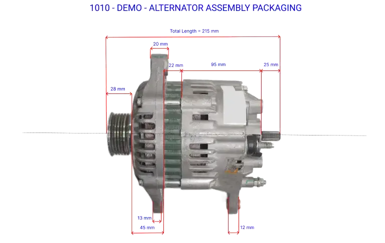
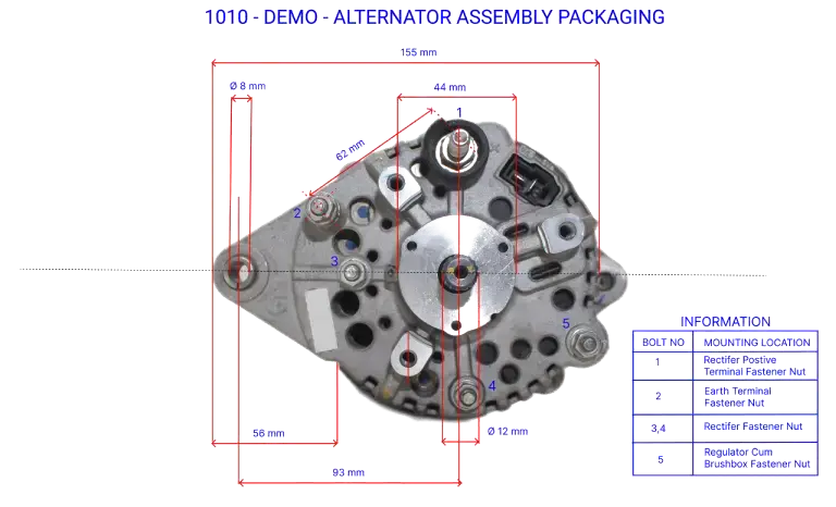
- Product/Sub-system packaging diagram.
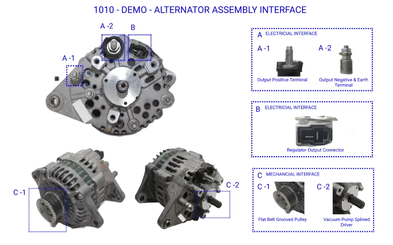
- Product/Sub-system interface diagram.
This is mapped for all products & all sub-systems. Once it is created, from the architecture analysis function on xcPEP stats can be generated.
1. Front View Packaging Architecture Representation
2. Top View Packaging Architecture Representation
3. Back View Packaging Architecture Representation
4. Mechanical and Electrical Interface Representation
5. Front Cross Section View Functional Representation
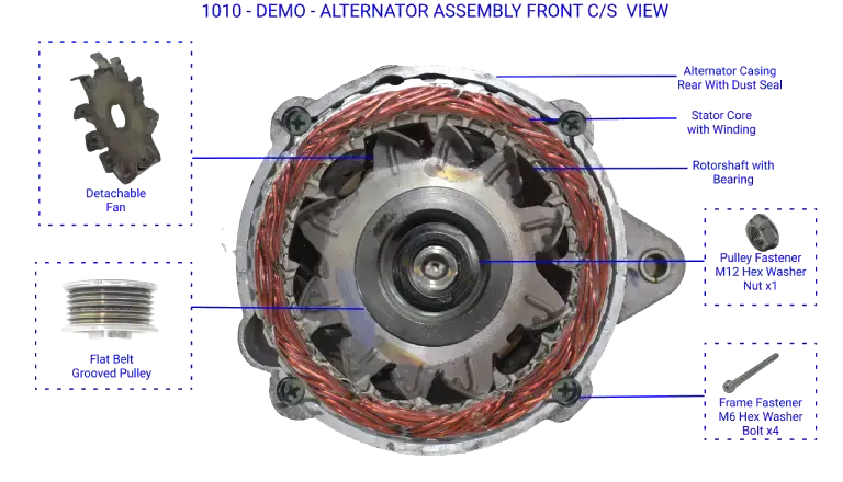
6. Top Cross Section View Functional Representation
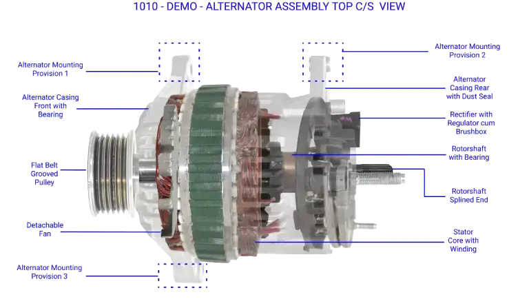
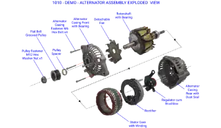
7. Exploded View Representation
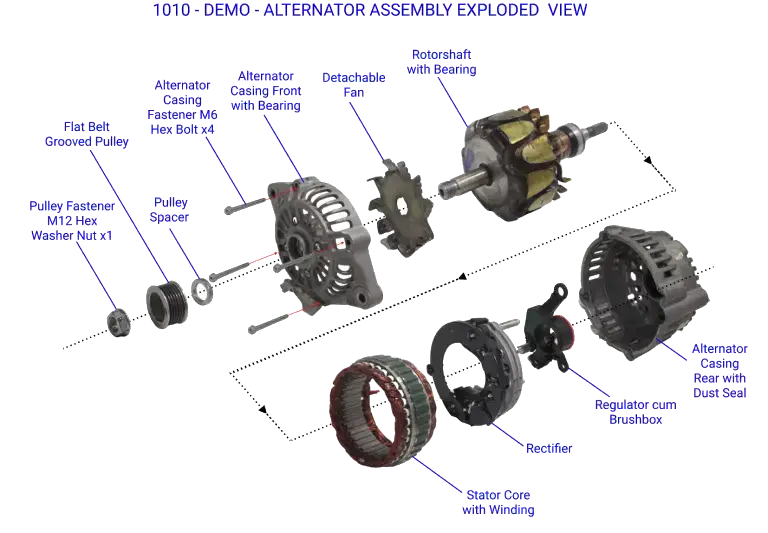
Feature Mapping
In the Feature module of xcPEP, the following are mapped:
- Feature: Features, USP of the product
- Specification: technical/other specs of the product
These parameters are mapped to feature module, and from feature analysis functions ideas are generated.
Features mapped
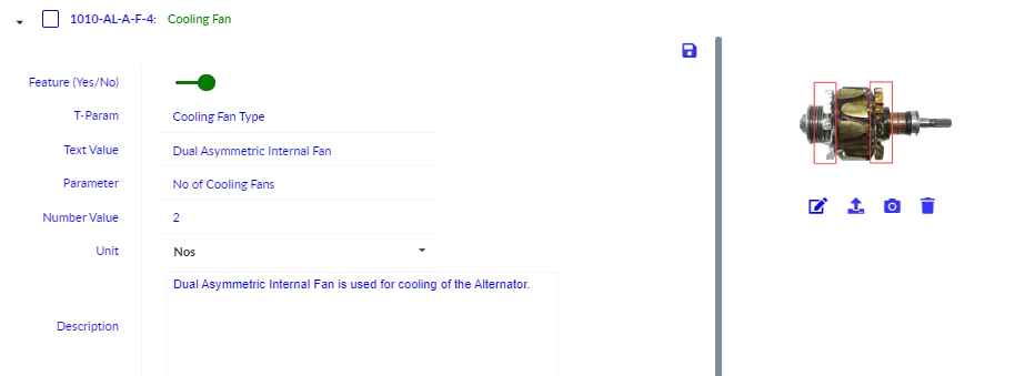
1. Cooling Fan – Dual asymmetrical internal fans with cowles impeller disc design present with one fan being detachable while other is spot welded to the rotor claw.
2. Casing Assembly – The casing is a split type design with front and rear casings which are held together using four hex washer bolts. The casings are made using cast aluminum which has vent gaps for cooling provision.
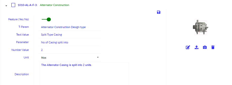
The casings are made using cast aluminum which has vent gaps for cooling provision.
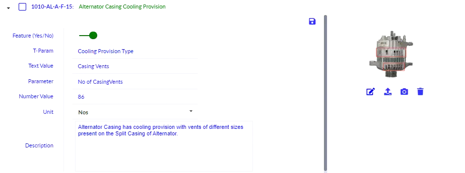
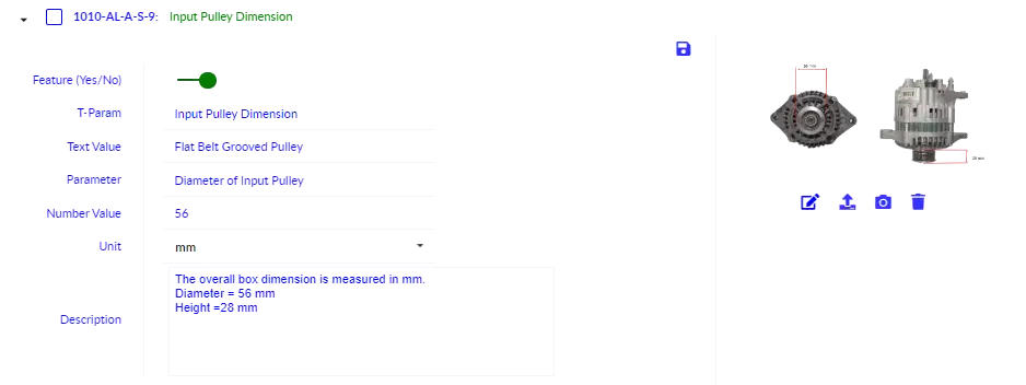
3. Input Driver Pulley Features – A solid flat belt grooved pulley type of pulley is present on the Alternator with zinc dichromate coating. There are five grooves present on the pulley with pitch distance of the grooves being 2.9 mm.
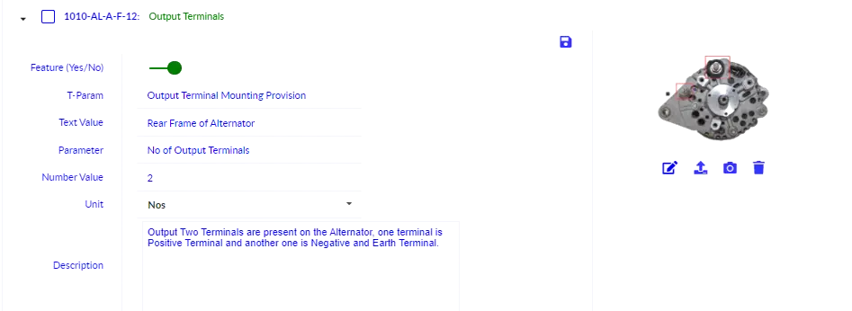
4. Output Terminals – There is one output positive terminal and a single terminal is provided for negative and earthing terminal mounting provision. The positive terminal has a protective shield for protection.
5. Stator Feature
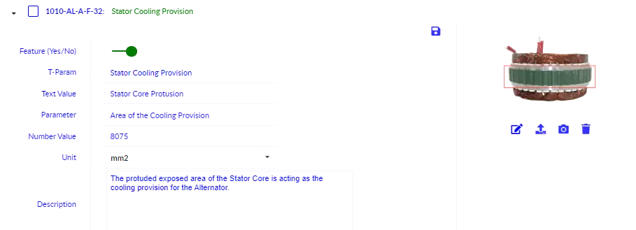
- Stator Core - Stacked laminated core plates are present on the alternator which are 40 plates in total and 36 semi- closed slots. These plates are riveted together with 5 air vent holes present on the core plates for cooling ventilation. The exposed stator core cooling area is coated with enamel to protect it from rusting. Stator slot insulators are placed in between each stator slot.
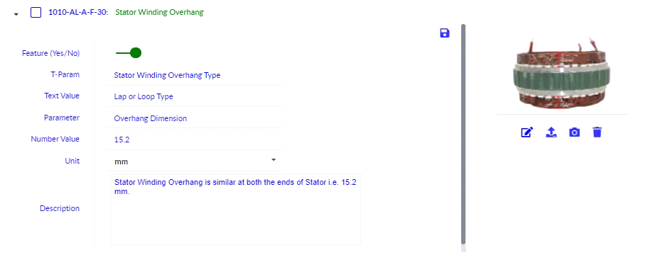
- Stator Winding - Enamel coated copper winding are looped wound to the stator core in 3 phase configuration. The connector ends of the winding’s have protective sheath covers.
6. Rotor Features
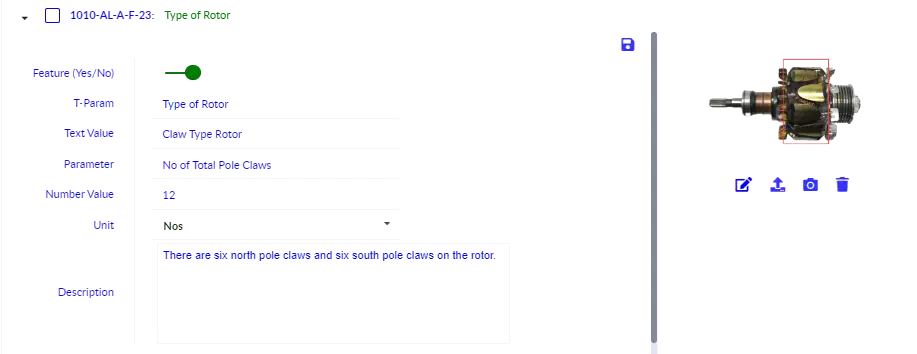
- Rotor - The rotor is of claw pole design with 12 claws with coil winding present between the claw poles. There are 2 slip rings present which are mounted on a plastic sleeve. There are balancing holes present on the rotor claws for rotation balancing. The whole rotor claw is coated with varnish for insulating the rotor claw from rotor coils.
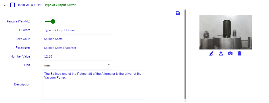
- Rotor shaft - The rotor shaft has splined teeth at one end which is the driver of the vacuum pump connected to alternator. There is a ball bearing on the splined end of the shaft.
Technical Specification Table
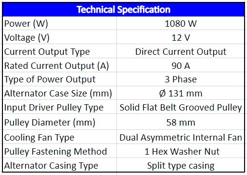
Product Level Teardown process & Its Significance
In the course of Product design and the development, Product Teardown is the process of taking apart a product to understand it and to understand how the company is making the product.
By disassembling the products, we can obtain the required data on how the particular component functions or usefulness of a particular feature or design.
Product teardown is required in depth competitive benchmarking. The design team must compare the performance with the competitive product.
Product Teardown Process
- Sub-System boundary identification & definition
- Finalize list of sub-systems & assign teardown sequence based on complexity
- Teardown sub-systems one by one while mapping information on packaging, features, functionality & complexity
- Parts & Assemblies teardown from sub-systems while mapping BOM parameters data
- Destructive teardown for next level teardown up to individual parts level
Torque Value
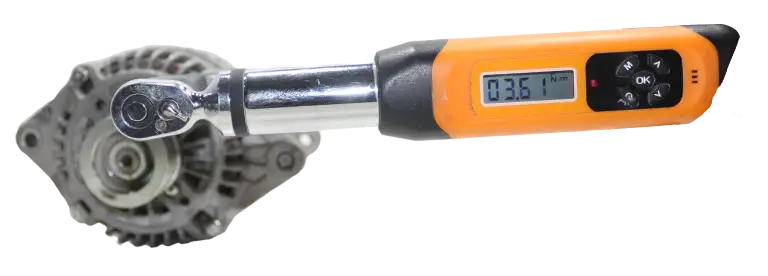
Torque Values Tables:
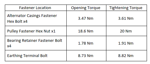
Teardown Activity
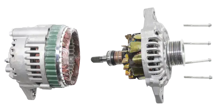
Disassembly of the Alternator Casing with removal of the 4 Hex Bolts

Disassembly of the Product to the Sub Assembly Level
Teardown Documentation

BOM and Teardown data on xcPEP
xcPEP has several such automation functions built in for teardown process automation. In certain areas, machine learning models trained on relevant parts and assemblies are used where typical codes and algorithms are not sufficient.
We map product level, sub-assemblies level and part details in very high detail leaving nothing to subjectivity. On the xcPEP platform, these data points are all interlinked which helps in analytics and inference drawing in real time. Parameters for a project are designed with the end objective and corresponding analysis in mind.
Creating of BOM sub-assemblies
In order to do in detail analysis of the Alternator Generator, we have divided it into five main sub-assemblies I.e., Rotor Assembly, Stator Assembly, Casing Assembly, Regulator Assembly and Rectifier Assembly.
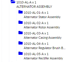
BOM data mapping
Product Level Data is first mapped with details like overall dimensions, weight, manufacturer or supplier details and 8 views of the product with isometric and information images are captured before teardown
