DJI Inspire 1 Drone Teardown and Costing
Motor Controller Teardown & Cost Driver Comparison
LCV Steering Pump Teardown & Benchmarking
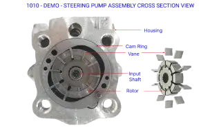
*All data/graphs/trends/images presented on this page are dummy/heavily masked/edited to remove specific details. They are intended only to showcase sample outcomes of such activities.
Recently we conducted VA/VE exercise on the Power Steering Pump used for commercial vehicle applications. Engineering insights are generated for study of packaging, integration, features, interface with other subsystems, and more. This blog contains our findings on the Power Steering Pump consisting of:
- Introduction to Power Steering Pump and its types.
- Disassembly and feature study of Power Steering Pump.
- Bill of materials generated from xcPEP.
- Architecture and layout study of Power Steering Pump.
What is a Power Steering Pump?
The Power Steering Pump is the heart of the hydraulic steering system. It converts rotational energy supplied by the engine into hydraulic energy. The Pump is driven by the engine via a belt and pulley. The pump contains a set of retractable vanes that spin inside an oval chamber. As the vanes spin, they pull hydraulic fluid from the inlet line at low pressure and force it into the outlet at high pressure.
Theory of Operation.
All pumps function by creating a partial vacuum at the inlet, which causes atmospheric pressure to force fluid into the pump from the reservoir. The pump then pushes this fluid into the system for use. The fluid is used to power the steering gear. Pump output flow relates to steering gear speed and pumps output pressure relates to steering gear force.
Types of Power Steering Pump.
Power steering systems date back to 1925 when they were first introduced by the Detroit pump manufacturer Vickers. Today they are standard on most vehicles. Different types of power steering pumps are used to power the steering system. The main difference between the different types of pumps is the design of the fins that move the steering fluid that is inside the pump and expelled through built-up pressure. They are all similar in that they contain a rotor inside the pump housing that spins. There are three different types of pumps used in power steering systems.
- Vane Power Steering Pump: Vane pumps are the most common type of power steering pump used. In this type of pump, the rotor is housed in an oval or elliptical-shaped housing where it turns. Vanes fitted to the outside diameter of the rotor sit against the housing walls as the rotor turns. When power steering fluid enters into the vane pump housing it is trapped between the vanes, the housing wall, and the rotor. A subsequent pressure increase causes the fluid to be pumped out of the housing and then through the outlet chambers.
- Roller Power Steering Pump: In a roller power steering pump, wide V-shaped grooves cut into the side of the rotor allow steel rollers to ride along the inside contour of the pump. The pump is contained in an oval-shaped housing within the pump body. Centrifugal force pushes the rollers to the oval’s outer edge where they trap fluid, similar to the way the vanes catch the fluid in a vane pump. The pressurized fluid is forced out through two outlets in the pump, driving the power steering system.
- Slipper Power Steering Pump: The slipper power steering pump has a rotor housed in an elliptical-shaped chamber that rotates within the body of the pump. Fitted into wide slots on the rotor are springs that are topped with scrubber-type “slippers.” The springs keep the slippers in constant contact with the wall of the pump. As fluid enters the pump, pressure is built up and released to drive the power steering system.
Power Steering Pump Chosen for the activity.
The Power Steering Pump we have chosen for the activity is the Vane Power Steering Pump.
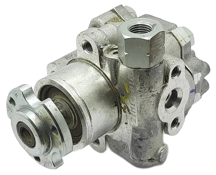
This blog will focus on our findings on Power Steering Pump in the following areas:
- Power steering Pump Architecture
- Feature mapping.
- Sub assembly level teardown.
- Rotor, Cam Ring, Vanes and other
- structural components.
- xcPEP’ s role in analysis
Architecture mapping
In the architecture module of xcPEP, the following are mapped:
- Product/Sub-system packaging diagram.
- Product/Sub-system Exploded View.
This is mapped for all products & all sub-systems. Once it is created, from the architecture analysis function on xcPEP stats can be generated.
1. Front View Packaging Architecture Representation
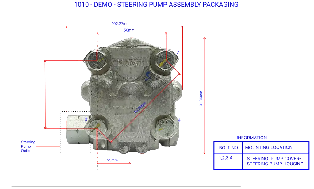
2. Back View Packaging Architecture Representation
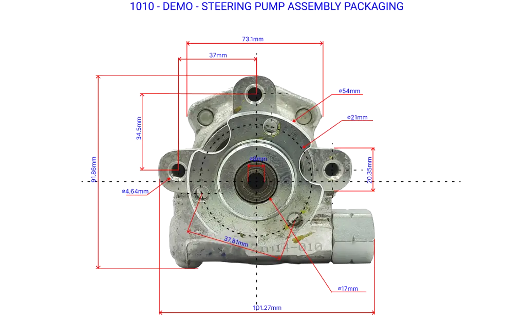
3. Left Side View Packaging Architecture Representation
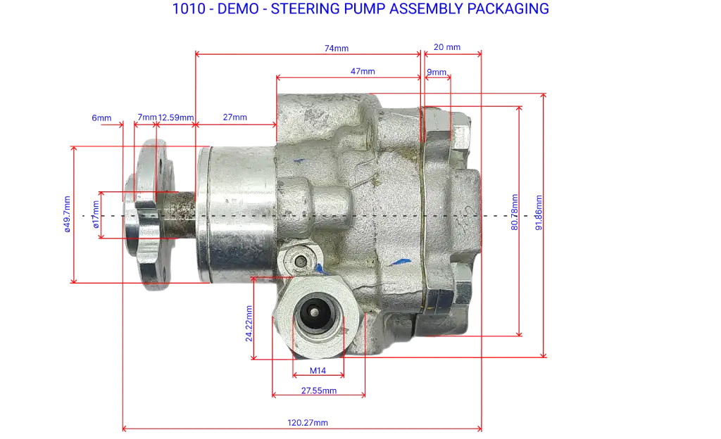
4. Bottom View Packaging Architecture Representation
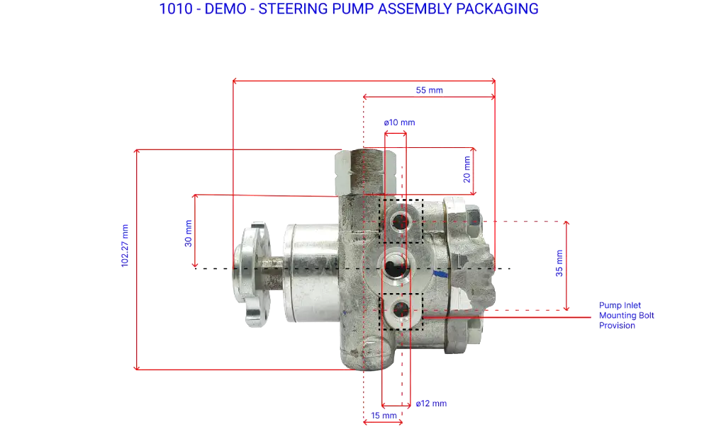
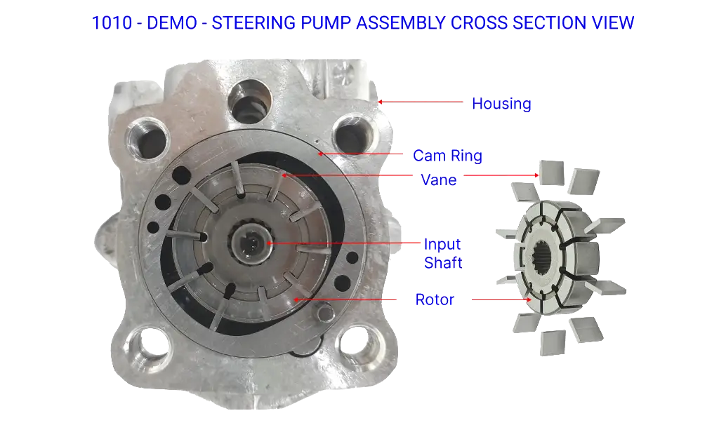
5. Cross Sectional View Representation
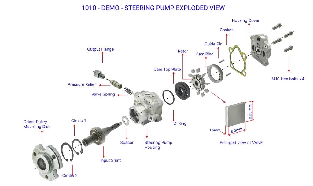
6. Exploded View Representation
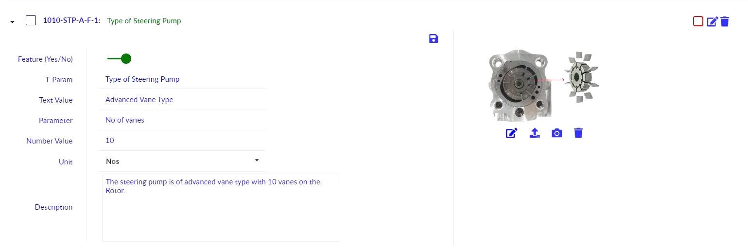
Feature Mapping.
In the Feature module of xcPEP, the following are mapped:
- Feature: Features, USP of the product
- Specification: technical/other specs of the product.
- Information.
These parameters are mapped to feature module, and from feature analysis functions ideas are generated.
Feature Mapped.
Type of Steering Pump – The Power Steering Pump is a balanced, positive displacement, sliding vane type two-line pump with internal pilot-operated flow control and relief valve. A total number of 10 Vanes fixed on Rotor is used to create high pressure for power steering operation.
Type of Pump Driver – The Steering pump is driven by the engine via a belt and pulley. The Pump Driver is Press fitted to the Input shaft and is mounted to Pulley via 3 bolts.
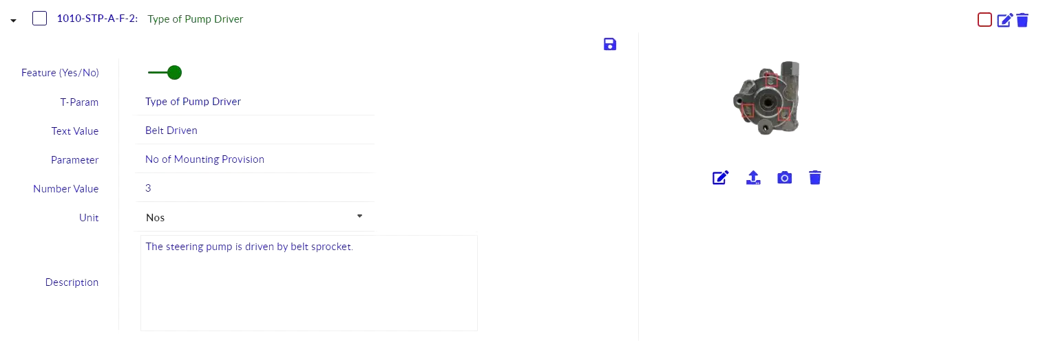
Steering Pump Mounting Provision – The steering Pump is mounted to the engine block using 3 M10 Hex bolts.

Steering Pump Cover Gasket – A Steering Pump Cover Gasket of 1.2 mm is used in between the Steering Pump Housing and Housing Cover to prevent hydraulic oil leakage.

Pressure Relief Valve– The Power steering Pump has a pilot operated relief valve built into the flow control valve which will limit the maximum pressure the pump can produce. When the pressure limit has been reached, the relief section will cause the flow control to bypass more oil internal to the pump, limiting the outlet pressure.

Rotor Driving Mechanism – The rotor is driven by a spline shaft that is mounted to the pulley, 10 vanes are placed in rotor slots which will move freely in the slots.

Guide Pin – Two guide pins are used to position the cam ring to the Steering Pump Housing Cover.

Specifications Mapped.
Inlet Dimension
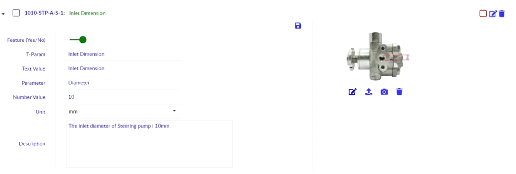
Outlet Dimension

Overall Part Dimension

Information Mapped.
Information Engraved
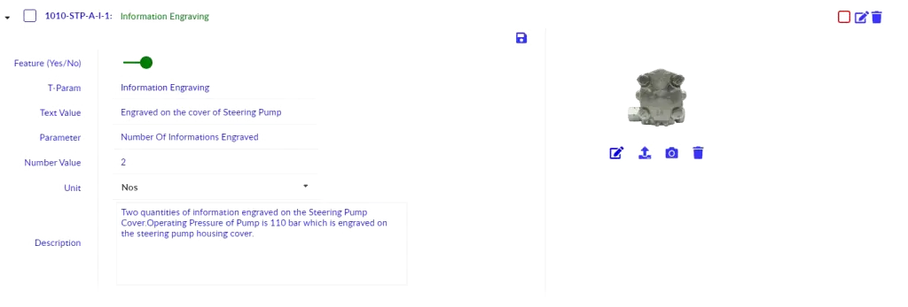
Product Level Teardown process & Its Significance
In the course of doing VA/VE to identify the areas of high cost and help to eliminate them product teardown is required. Product Teardown is the process of taking apart a product to understand it and to understand how the company is making the product. In simple words the process of disassembling a part to understand how it has been made and its functionalities are known as product teardown. A product teardown process is an orderly way to know about a particular product and identify its parts, and system functionality to recognize modelling improvement and identify cost reduction opportunities. Unlike the traditional costing method, tear-down analysis collects information to the last level of a specific part which helps to evaluate the cost required to manufacture the part. Companies can understand their competitor’s product and on what grounds it differs from their own product and the manufacturing cost associated.
The three primary reasons for a product teardown study are:
- Breakdown and Analysis.
- Benchmarking & Costing.
- Knowledge and product improvement.
Product Teardown Process
The following are the general key steps followed for performing the teardown activity at ASI:
- Sub-System boundary identification & definition
- Finalize list of sub-systems & assign teardown sequence based on complexity
- Teardown sub-systems one by one while mapping information on packaging, features, functionality & complexity
- Parts & Assemblies teardown from sub-systems while mapping BOM parameters data
- Destructive teardown for next level teardown up to individual parts level
Torque Value
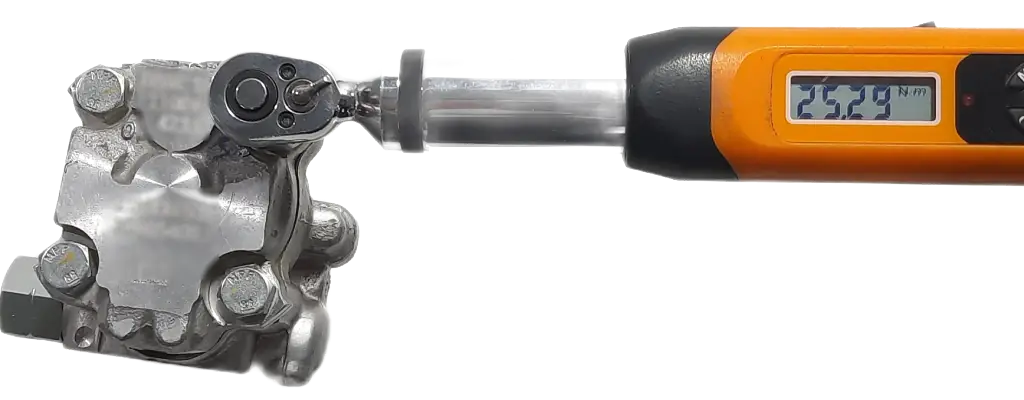
Before the disassembly of the product into sub system level, the torque values of all the fastening bolts are measured using a torque wrench. The opening torque and tightening torque value measurement are in the following table.
Torque Values Tables:

Teardown Activity
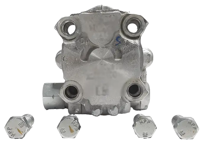
Disassembly of the Power Steering Pump Casing
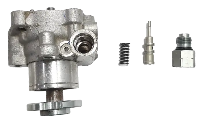
Disassembly of Pressure Relief Valve
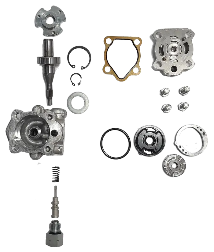
Exploded View of Power Steering Pump
Teardown Documentation
Detailed documentation of the teardown is captured through images and is uploaded to xcPEP site for teardown study. Images are taken before and after teardown of a part for future reference and exploded view of the product is taken after complete teardown.
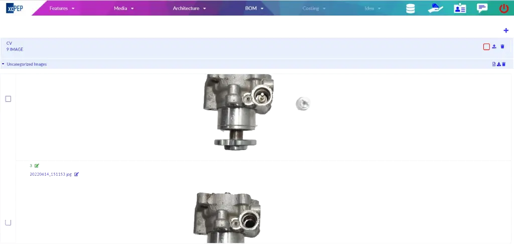
BOM data on xcPEP
xcPEP has several automation functions built in for teardown process automation. In certain areas, machine learning models trained on relevant parts and assemblies are used where typical codes and algorithms are not sufficient.
We map product level, sub-assemblies' level and part details in very high detail leaving nothing to subjectivity. On the xcPEP platform, these data points are all interlinked which helps in analytics and inference drawing in real time. Parameters for a project are designed with the end objective and corresponding analysis in mind.
Creating of BOM
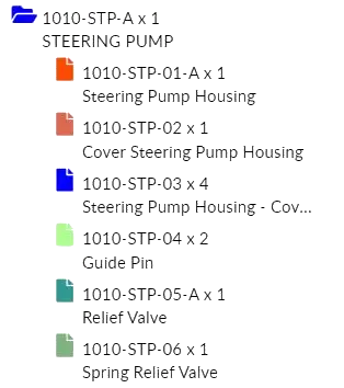
BOM data mapping
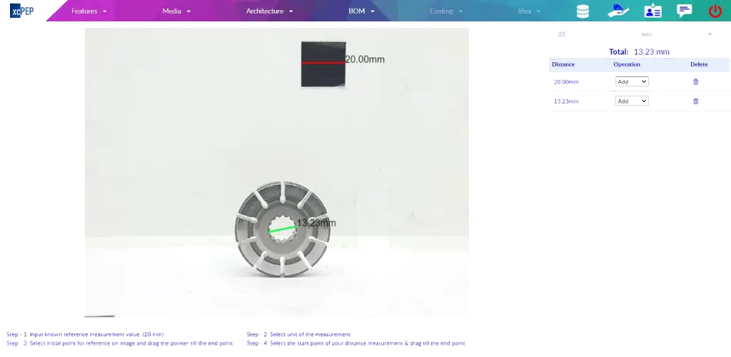
Product Level Data is first mapped with details like overall dimensions, weight, manufacturer or supplier details and 8 views of the product with isometric and information images are captured before teardown. After teardown the child parts are created in xcPEP for data mapping.
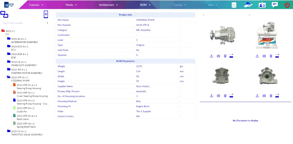
BOM Image Analysis
Image analysis with machine learning algorithms is used to find specific packaging dimensions of a part. Machine learning algorithms can be trained to recognize specific objects, patterns and shapes in images to gather quantitative information, thereby optimizing and accelerating image analysis.
