Automotive Should Costing
Executed by ASI Engineering. Powered by xcPEP — should-cost analysis software for accurate, process-based cost modeling
Should costing is a data-driven cost estimation approach used by automotive manufacturers to determine what a part, component, or system should cost based on its material, geometry, manufacturing process, and sourcing region. Unlike supplier quotes, which often lack transparency, should costing methodology builds cost logic from the ground up to establish internal benchmarks, uncover cost-saving opportunities, and support fact-based commercial negotiations.
At ASI, automotive should costing is executed by ASI Engineering — a dedicated team focused on delivering highly accurate and transparent estimates for the automotive industry. Our experts use a combination of teardown insights, dimensional mapping, and manufacturing process modeling to replicate real production scenarios. Every estimate is built using xcPEP, our proprietary should-cost analysis software, and xcPROC, our validated cost data hub. ASI Engineering supports OEMs and Tier 1 suppliers across the full range of vehicle platforms, including passenger cars, commercial trucks, electric buses, two-wheelers, three-wheelers and hybrid systems.
For every part analyzed, the team builds a manufacturing cost structure that reflects actual shop floor conditions, using ASI’s proprietary platforms, xcPEP and xcPROC, to structure and validate each model.
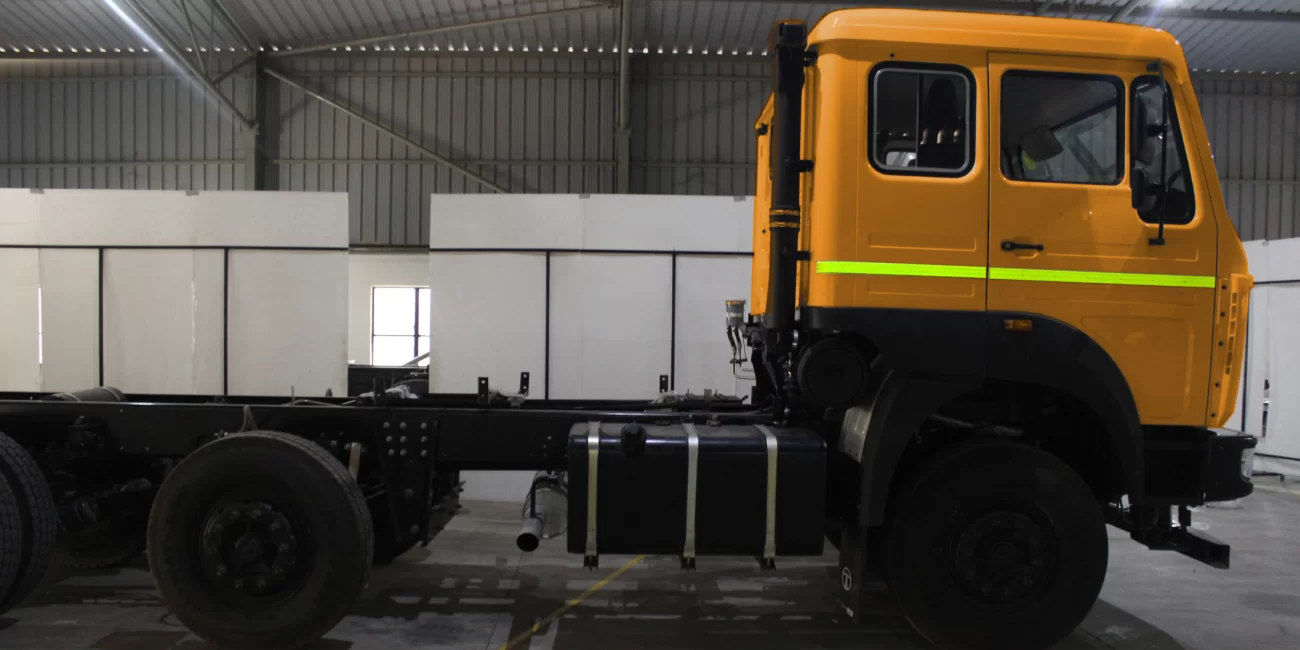
To convert teardown data or drawings into actionable insights, ASI Engineering relies on xcPEP, our proprietary should-cost analysis software designed for real manufacturing conditions. xcPEP enables teams to create structured, part-level cost models using actual process flows, region-specific input rates, and engineering parameters—making it a powerful should cost model software. When used alongside xcPROC, our cost data hub, it becomes a complete should cost solution that supports target costing, competitor cost benchmarking, and early design decision-making.
This setup ensures consistent application of a proven should costing methodology across automotive programs. By replacing fragmented spreadsheets with reliable and repeatable models, xcPEP helps OEMs and Tier 1 suppliers drive effective cost reduction initiatives in complex automotive partnerships—all within a unified, scalable should cost modelling software.
Detailed Data Mapping using xcPEP
To the extent of over 2 million data points mapped for a typical car makes our should costing precise and useful for decision making.
Accurate should costing starts with capturing the right inputs at the right level of detail. The ASI Engineering team begins by mapping part-level data based on how each component is actually manufactured. This information is gathered through physical teardown, interpretation of 2D drawings, or direct extraction from CAD models, depending on what is available for the part. This forms the foundation for creating structured cost models inside xcPEP, our proprietary should-cost analysis software.
For every part studied, the ASI Engineering team captures geometry, material specifications, and manufacturing process parameters that influence cost. The specific inputs depend on the production method. Stamped parts may require blank size, thickness, and feature count. Molded parts are defined by bounding box dimensions, wall thickness, and part weight.
This data is used to generate the part’s bill of materials inside xcPEP, the should-cost analysis software, where each parameter is recorded in a structured format. From this BOM, the relevant inputs are fed into cost models built specifically for the part’s manufacturing process. These models simulate each operation using real machine data, labour inputs, and regional assumptions, resulting in a calculated cost that reflects how the part would be produced on a shop floor.
In a typical vehicle program, such as a passenger car or electric four -wheeler, the ASI Engineering team maps over two million individual data points across parts and processes to support detailed cost estimation.
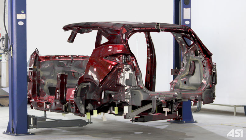
By structuring part-level inputs in xcPEP, ASI Engineering enables teams to move away from unstructured spreadsheets and adopt a consistent, scalable should cost solution. xcPEP serves as a comprehensive should-cost analysis software, offering a unified environment to run cost simulations, build fact packs for supplier negotiations, and track cost-saving ideas. Adopted by leading automotive OEMs and Tier 1 suppliers, xcPEP supports target costing for new product development, competitor cost benchmarking and structured cost reduction studies. xcPEP reinforces a standardised should costing methodology, helping teams drive alignment across sourcing, engineering, and finance functions within complex automotive partnerships.
Part Geometry Mapping
ASI Engineering teams maps part details at a level of precision that goes far beyond standard BOM templates. For every component, the team records dimensional inputs, material details, supplier information, mounting method, and manufacturing category—based on teardown data, 2D drawings, or CAD data. xcPEP uses this data to determine the most suitable cost model, making it a powerful should-cost analysis software for part-level should costing.
In electronic assemblies such as PCBs, each child part and subcomponent are mapped individually. Attributes such as manufacturer name, part number, quantity, board location, and mounting type are captured for every child part. For mechanical parts, the BOM includes detailed measurements such as box size, surface area, and perimeter, along with raw material specifications like grade and form. Where applicable, the team conducts lab testing to determine material composition, and certified test reports are uploaded directly to the BOM. Elemental breakdown, chemical values, and test methods are stored in structured fields for traceability. By combining validated material data with precise part geometry, xcPEP, our should-cost analysis software ensures accurate and repeatable process selection across all sourcing scenarios.
All data is organized within xcPEP, where each parameter is linked to cost models and is available for comparison across projects. This structured approach enables part level costing that is consistent, auditable, and production ready.
Accurate Raw Material Identification
ASI Engineering does not assume or visually guess material type. For every part, the material grade and form are identified through teardown and confirmed through lab testing. Standard methods such as chemical composition analysis, XRF, and spark testing are used to determine the exact material properties.
Once identified, the material such as CRCA steel, aluminum 6061 T6, or PA66 with glass filler is recorded at the part level and added to the BOM. The corresponding material test report is uploaded to the BOM, ensuring complete traceability. After this step, xcPEP fetches region specific pricing from xcPROC so that the material cost reflects both the correct grade and the actual sourcing location.
Material identification also affects downstream costing. The selected material impacts tool selection, machining effort, welding parameters, and cycle time. Confirming it at the start ensures that all process logic in the model is based on real production behavior.
Detailed Manufacturing Process Calculation
ASI Engineering team maps every manufacturing process involved in producing the part. Based on teardown observations, drawings, and CAD data, the team identifies each operation, whether it is stamping, welding, machining, molding, painting, or assembly. For every process, a dedicated cost model is built using inputs drawn directly from the BOM. Parameters such as material type, part geometry, feature complexity, machine used, cycle time, tool wear, and scrap rate are configured based on how the part would be made in an actual plant.
These models are not based on fixed templates. Instead, ASI Engineering defines each input according to the part’s specific characteristics and manufacturing method. A casting process may include shot weight, die life, and cooling time, while a machining process may require tool path length, feed rates, and surface finish conditions. xcPEP applies a structured should costing methodology to simulate these operations using real manufacturing rules, not assumptions.
These validated flows are built with xcPEP’s structured should costing methodology, mirroring real shop-floor behaviour in every calculation. All cost models are built inside xcPEP and calculated using validated input values from xcPROC, including machine hour rates, labor costs, and regional overheads. This ensures that each cost output reflects real production behavior, not just theoretical design assumptions.
Machine Identification & MHR Calculation
ASI Engineering identifies the specific machine required for each manufacturing operation during the costing process. This selection is based on part geometry, material, process type, and production scale. Whether the process involves stamping, injection molding, CNC machining, or welding, the team maps the right machine class and capacity that would be used in an actual production setting.
Each machine entry includes detailed attributes such as capital cost, installation cost, life in years, effectiveness, power consumption, maintenance rate, and bed size. These inputs are used to calculate the Machine Hour Rate, which reflects the true operating cost of that equipment over time. xcPEP uses these parameters to simulate machine costs at an operation level, making it a complete should cost solution for real-world costing.
Labour Skill Identification & LHR Calculation
ASI Engineering identifies the labour required for each manufacturing operation by analyzing the nature of the task, the level of automation, and the skill required to perform it. For every step in the process—whether it is manual welding, press loading, deburring, or quality inspection—the team defines the type of labour needed, including operator grade, crew size, and working shifts.
Each labour role is assigned a Labour Hour Rate that reflects region specific wage structures, statutory benefits, shift allowances, and productivity assumptions. These values are sourced from xcPROC and mapped within xcPEP, ensuring that labor costs are consistent with actual plant conditions. This is a key differentiator of xcPEP as a should cost analysis tool—unlike legacy costing tools or spreadsheets, xcPEP enables region-specific labour modelling tied to real skills, processes, and plant conditions.
Actual Logistics Calculation
ASI Engineering calculates logistics cost based on how the part would be packaged, stored, and transported in an actual supply chain. This includes defining packaging format, container type, stack density, and the number of parts per shipment. For each part or assembly, the team evaluates both inbound and outbound logistics based on source and destination plant locations.
Freight cost is calculated using transport mode, distance, loading efficiency, and fuel or carrier rates. Where applicable, import duties, taxes, and documentation costs are added to account for cross-border movement. For domestically sourced parts, the cost model reflects local freight rates, route conditions, and packing density based on part geometry. All of this is simulated within xcPEP, the should cost software, so that logistics costs reflect actual routing, packaging, and freight conditions—not broad assumptions.
Currency Exchange and Import Cost Impact
ASI Engineering accounts for the cost impact of currency exchange when parts or materials are sourced internationally. For every imported item, the team factors in the applicable exchange rate, import duty, transaction charges, and customs handling fees.
Exchange rates are not assumed. They are mapped based on sourcing country and time frame, using validated input data from xcPROC. The team models both short term and long-term sourcing scenarios to reflect real supplier setups and logistics flows. This capability strengthens xcPEP’s value as a should cost solution by helping teams evaluate the total cost of sourcing across borders.
Realistic Overhead Calculation
ASI Engineering maps overheads in detail rather than applying a flat percentage. The team defines individual cost components such as machine overhead, labour overhead, tool overhead, setup cost, rejection losses, and profit separately based on how each is actually incurred during production.
These values are calculated inside xcPEP using inputs like cycle time, tool life, operator involvement, and process scrap. This approach allows overhead to be applied in a way that reflects real plant behavior, not estimates, enabling better cost visibility and control. This structured overhead calculation is a fundamental aspect of the should costing methodology built into xcPEP, differentiating it from traditional cost estimation methods.
Should Cost Models for Automotive Should Costing
Comprehensive, process-wise costing built inside xcPEP by ASI Engineering.
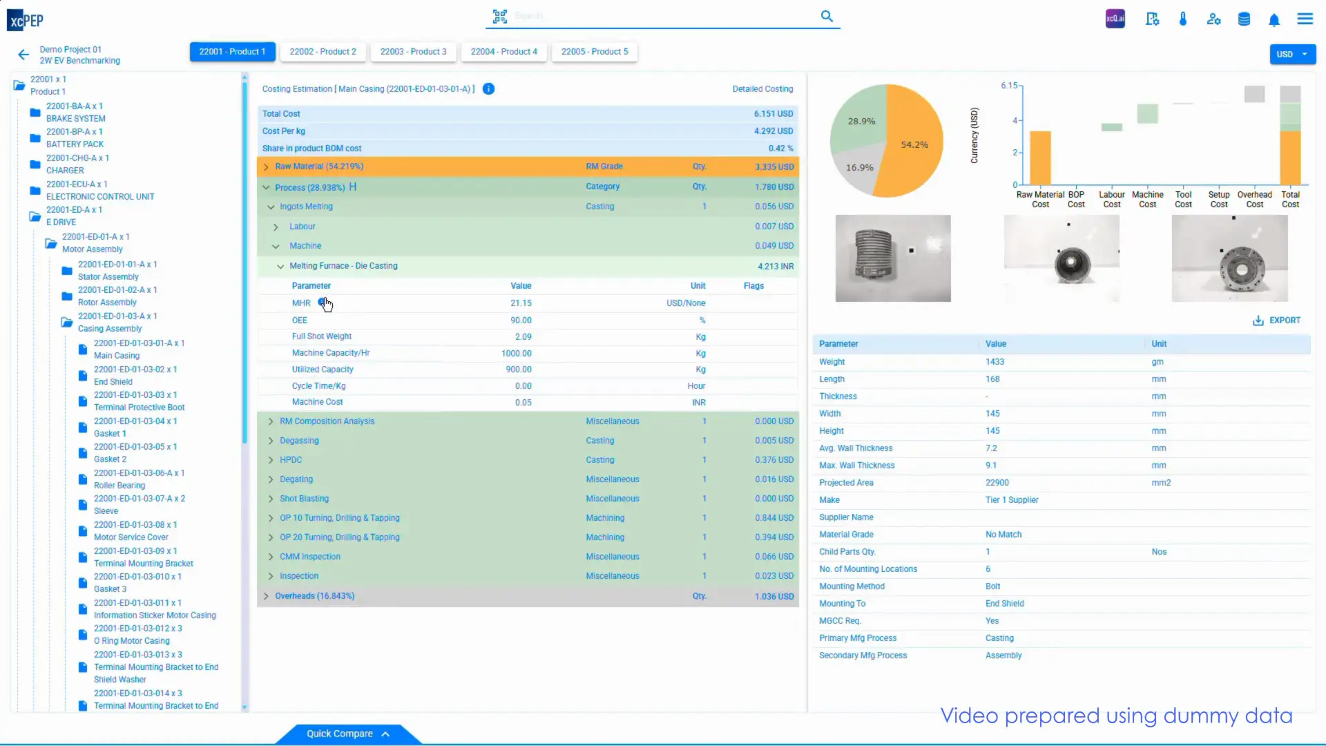
Automotive should costing begins with clean, process-wise cost models. At ASI Engineering, we build part-level models using actual manufacturing logic—routing, machine time, tool wear, and regional cost inputs. All models are created inside xcPEP, our structured should cost analysis software, and are used by OEMs and Tier-1s for design validation, supplier benchmarking, and cost reduction.
From injection moulding and stamping to machining, testing, and packaging, each process is modelled using our proven should costing methodology. This ensures consistency, traceability, and speed in every automotive should costing engagement.
Should Cost Models for Plastic Moulding

- Film Packaging
- Polyethylene (PE) Films
- Polypropylene (PP) Films
- Polyethylene Terephthalate (PET) Films
- Biaxially Oriented Polypropylene (BOPP)
- Cast Polypropylene (CPP)
- Biaxially Oriented Polyester (BOPET)
- Amorphous Polyester (APET)
Thermoforming
- Vacuum Forming
- Pressure Forming
- Drape Forming
- Twin-Sheet Forming
- Foam Moulding
- Structural Foam Moulding
- Architectural Foam Moulding
- Foam Crown Moulding
- Stucco Foam Trim
- EPS Shape Moulding
Extrusion Moulding – Plastic & Ceramic
- Direct (Forward) Extrusion
- Indirect (Reverse) Extrusion
- Hydrostatic Extrusion
- Blown Film Extrusion
- Sheet/Film Extrusion
- Tubing Extrusion
- Coextrusion
- Extrusion Coating
Plastic Rota Moulding
- Clamshell Machine
- Shuttle Machine
- Carousel Machine
Injection Moulding – Thermoplastic
- High-Pressure Injection
- Micro Injection Moulding
- Gas-Assisted Injection
- Thin-Wall Packaging Moulding
Injection Moulding – Thermoset
- Transfer Moulding
- Compression Moulding
- Reaction Injection Moulding (RIM)
- Blow Moulding
- Extrusion Blow Moulding
- Injection Stretch Blow Moulding
- Accumulator Head Blow Moulding
Should Cost Models for Rubber Moulding

- Compression Moulding – Rubber
- Hydraulic Compression Moulding
- Transfer Compression Moulding
- Preformed Rubber Blank Moulding
- Closed Mold Curing
- Rubber Sheet Moulding
- Extrusion Moulding – Rubber
- Hot Feed Extrusion
- Cold Feed Extrusion
- Microwave Curing Extrusion
- Steam Vulcanization Extrusion
- Salt Bath Curing
- Autoclave Curing
- Injection Moulding – Rubber
- Liquid Injection Moulding (LIM)
- Vacuum Injection Moulding
- Rubber Transfer Injection
- Cold Runner Injection Moulding
- Injection Moulded Seals & Gaskets
- Extrusion Moulding – Rubber & Plastic
- Dual Extrusion (Hard-Soft Combinations)
- Co-extruded Weather Seals
- TPV and EPDM Hybrid Extrusion
- Rubber-Plastic Strip Profiles
- Edge Trim Extrusion
Should Cost Models for Metal Forming

- Cold Forging
- Cold Heading
- Cold Extrusion
- Cold Impact Extrusion
- Coining
- Cold Roll Forging
Ferrous Casting – Sand Casting
- Green Sand Casting
- Resin-Bonded Sand Casting
- No-Bake Sand Casting
- Shell Moulding
- Lost-Foam Casting (Ferrous)
Hot Forging – Gear
- Upset Forging of Gear Blanks
- Cogging
- Skiving & Burnishing
- Finish Forging
Hot Forging – Crankshaft
- Preform Forging
- Rotary Forging
- Impression-Die Forging
- Finish Forging & Trimming
- Powder Metallurgy
- Cold Press & Sinter
- Hot Isostatic Pressing (HIP)
- Metal Injection Molding (MIM)
- Powder Forging
Spring – Cold Wound
- Compression Spring Coiling
- Extension Spring Coiling
- Torsion Spring Coiling
- Wire Straightening & Stress Relieving
Spring – Hot Wound
- Hot Coil Winding
- Ring Spring Forming
- Shot Peening
- Annealing
Substrate – Metallic
- Aluminum Substrate Bonding
- Copper Core Substrates
- Metal-Insulated Substrates (IMS)
- Heat-Sink Metal Cores
- Zinc Casting – HPDC
- Hot-Chamber Die Casting
- Cold-Chamber Die Casting
- Vacuum Die Casting (Zinc)
- Squeeze Casting
Zinc Casting – GDC
- Tilt-Pour Gravity Casting
- Low-Pressure GDC
- Slush Casting
- Permanent-Mould Casting
Aluminium Casting – HPDC
- Cold-Chamber HPDC
- Hot-Chamber HPDC
- Vacuum HPDC
- High-Pressure Die Casting (Al Alloys)
Aluminium Casting – GDC
- Tilt-Pour Permanent-Mould Casting
- Slush Casting
- Low-Pressure Permanent-Mould
- Semi-Solid Rheo Casting
- Brass Casting – LPDC
- Bottom-Fill LPDC
- Counter-Gravity LPDC
- Semi-Solid LPDC
- Hot-Chamber LPDC
Brass Casting – GDC
- Tilt-Pour Gravity Casting
- Permanent-Mould GDC
- Centrifugal Casting (Brass)
- Sand-Mould Gravity Casting
Hot Forging – Roll
- Cogging-Mill Roll Forging
- Controlled Rolling
- Ring Rolling
- Scale-Breaker Rolling
Hot Forging – Closed Die
- Impression-Die Forging
- Flashless Forging
- Flash-Type Forging
- Precision Forging
Should Cost Models for Metal Fabrication

- Fabrication – Sheet Metal
- Laser Cutting
- Shearing
- Press Brake Bending
- Punching & Notching
- Roll Forming
- Deburring & Finishing
Machining – Gear
- Gear Hobbing
- Gear Shaping
- Gear Grinding
- Gear Broaching
- Gear Heat Treatment
- Fabrication – Structural & Others
- Steel Beam & Plate Welding
- Pipe & Tube Spooling
- Chassis & Frame Assembly
- Sheet Lamination
Metal Hose Assembly
- Spiral‐Wound Hose
- Braid Reinforced Hose
- Corrugated Hose
- PTFE Lined Hose
- Swaging & End Fitting
Stamping – Progressive Die
- Multi-station Strip Feeding
- Cutting, Forming & Piercing
- Progressive Coil Processing
- Stamping – Transfer Die
- Individual Blank Feeding
- High-Speed Compound Operations
- Automated Part Transfer
Stamping – Compound Die
- Simultaneous Cutting & Forming
- Deep Draw & Embossing
- High-Tonnage Presses
Cutting & Ablation
- Laser Cutting
- Plasma Cutting
- Waterjet Cutting
- Oxy-Fuel Cutting
- Welding & Joining
- MIG / MAG Welding
- TIG Welding
- Spot Welding
- Friction Stir Welding
- Laser Welding
Surface & finishing
- Grinding & Polishing
- Powder Coating
- Anodizing
- Galvanizing
Should Cost Models for Electrical

- Connectors
- Wire-to-Wire Connectors
- Wire-to-Board Connectors
- Board-to-Board Connectors
- Terminal Blocks
- Automotive Sealed Connectors
Electrical Cable
- Shielded Power Cable
- Coaxial Cable
- Ribbon Cable
- High Voltage Cable
- EV Battery Cables
Cell
- Cylindrical Cell
- Prismatic Cell
- Pouch Cell
- LFP / NMC / NCA Chemistries
- Cell Terminal Configurations
Display
- LCD Panel
- LED Backlit Display
- OLED Display
- Touch Panel (Capacitive / Resistive)
- TFT Module
- PCB – Aluminium
- Single Layer Aluminium PCB
- IMS (Insulated Metal Substrate)
- High Thermal Conductivity Types
- LED Application Boards
PCB – Copper
- Heavy Copper PCB
- High Frequency PCB
- Multilayer Copper Core
- RF Power PCBs
PCB – FR4
- Standard FR4 PCB
- Multilayer FR4 PCB
- Rigid-Flex FR4
- High Tg FR4
PCB – Ceramic
- Alumina Ceramic PCB
- Aluminium Nitride PCB
- Direct Bonded Copper (DBC)
- Low-Temperature Co-fired Ceramic (LTCC)
- PCB – Flexible
- Single-Sided Flex PCB
- Double-Sided Flex PCB
- Rigid-Flex PCB
- Polyimide Substrate
Bare PCB – 1 Layer
- FR4 / CEM1
- HASL Finish
- Basic Copper Thickness
Bare PCB – 2 Layer
- FR4 / Aluminium
- Via Drilling
- ENIG / OSP Finishing
Bare PCB – 4 Layer
- Signal-Ground-Signal-Ground Stackup
- Controlled Impedance
- Via-in-pad Design
- Bare PCB – 6 Layer
- Power-Ground Separation
- High-Speed Signal Routing
- Blind & Buried Vias
Bare PCB – 8 Layer
- Advanced Multilayer Stackup
- High-Density Interconnect (HDI)
- Thermal Management Layers
Stator
- Laminated Core Stator
- Hairpin Wound Stator
- Slotted vs Slotless Stator
- Die Cast Winding
Rotor
- Squirrel Cage Rotor
- Interior Permanent Magnet (IPM)
- Surface PM Rotor
- Wound Rotor Construction
Should Cost Models for Machining

- Drilling
- Standard Twist Drilling
- Deep Hole Drilling
- Gun Drilling
- Pilot & Reaming
Tapping
- Hand Tapping
- Machine Tapping
- Blind Hole Tapping
- Thread Forming
Turning
- External Turning
- Facing on Lathe
- Grooving & Parting
- Thread Turning
Milling
- Face Milling
- Slot Milling
- Profile Milling
- End Milling
Threading
- Single-Point Thread Cutting
- Rolling Dies
- Thread Milling
- Facing
- Lathe Facing
- Plunge Facing
- Facing in Chuck Work
Broaching
- Internal Keyway Broaching
- External Surface Broaching
- Rotary Broaching
Grinding
- Surface Grinding
- Cylindrical Grinding
- Centerless Grinding
- Tool Grinding
Boring
- Line Boring
- Jig Boring
- Horizontal Boring
Notching
- Tube Notching
- Sheet Metal Corner Notching
- Angle Notching
- Laser Cutting
- Fiber Laser
- CO₂ Laser
- Pulse Laser for Microcutting
Honing
- Manual Honing
- Vertical Honing
- Plateau Honing (Automotive)
Gear Hobbing
- Spur Gear Hobbing
- Helical Gear Hobbing
- Spline Cutting via Hobbing
Gear Shaping
- Internal Gear Shaping
- External Gear Shaping
- Timing Gear Shaping
Gear Shaving
- Radial Infeed Shaving
- Diagonal Shaving
- Underpass Method
- Gear Grinding
- Profile Grinding
- Generating Grinding
- Form Grinding
Shot Blasting
- Steel Grit Blasting
- Wheel Blast Systems
- Shot Blast Cleaning
Shot Peening
- Air Blast Peening
- Gravity Peening
- Saturation Peening
Sand Blasting
- Suction Sandblasting
- Pressure Blasting
- Abrasive Media Selection
Lapping
- Flat Lapping
- Cylindrical Lapping
- Polishing and Final Finishing
Should Cost Models for Welding & Joining

- MIG / MAG Welding
- Carbon Steel MIG
- Stainless MAG
- Pulse MIG for Aluminum
TIG Welding
- Manual TIG
- Orbital TIG
- Thin Section Welding
- Spot Welding
- Projection Spot Welding
- Cross Wire Welding
- Resistance Spot Weld
Friction Stir Welding
- Aluminum Profile Joining
- Tool Steel Weld Head
- Automated Linear FSW
- Laser Welding
- Keyhole Welding
- Conduction Welding
- Fine Micro-Welds
Ultrasonic Welding
- Plastic Ultrasonic Welding
- Wire Splicing
- Battery Tab Welding
- Riveting / Clinching
- Solid Riveting
- Blind Riveting
- Mechanical Clinching
Should Cost Models for Surface Finishing

- Powder Coating
- Epoxy Powder Coat
- Polyester Powder Coat
- Hybrid Powder Finishes
Electroplating
- Nickel Electroplating
- Zinc Plating
- Chrome Plating
- Anodizing
- Type II Color Anodizing
- Type III Hard Anodizing
- Clear & Black Coatings
Galvanizing
- Hot-Dip Galvanizing
- Electrogalvanizing
- Dry Coating Post-Galv
- Passivation
- Citric Acid Passivation
- Nitric Acid Process
- Stainless Steel Surface Prep
- Deburring & Polishing
- Tumbler Finishing
- Vibratory Deburring
- Buffing & Brushing
Should Cost Models for Testing & Inspection

- Dimensional Inspection
- CMM Inspection
- Height Gauge / Vernier
- Go/No-Go Gauge
Visual Inspection
- Manual Surface Check
- Visual Defect Sorting
- Deflash / Burr Check
- X-Ray & CT
- Die-Cast Void Inspection
- Battery Cell CT Scan
- BGA Package X-Ray
- Hardness & Microstructure
- Rockwell / Vickers Testing
- Metallographic Etching
- Grain Size Analysis
- Leak & Pressure Testing
- Helium Leak Test
- Air Decay Test
- Hydrostatic Pressure Test
Should Cost Models for Packaging & Logistics
- Export Packaging
- Palletized Crates
- Heat-Treated Wood (ISPM 15)
- Heavy-Duty Shrink Wrap
Returnable Packaging
- Plastic Bin Systems
- Metal Returnable Cages
- Foldable Crates
- Thermoformed Trays
- Anti-Static Trays
- Custom Molded Cavities
- Conductive Tray Systems
- Labeling & Identification
- Barcode Printing
- Part ID & QR Labels
- Compliance Tagging (RoHS, REACH)
- Final Assembly Packing
- Subassembly Kits
- Cushioned Inserts
- Operator Instruction Leaflets
Miscellaneous Should Cost Models for Automotive
Booklet
- Saddle Stitch Binding
- Perfect Binding
- Wiro Binding
- Folded Leaflet Assembly
- UV Coating & Lamination
Composite
- Prepreg Layup
- Vacuum Bagging
- Resin Transfer Moulding (RTM)
- Autoclave Curing
- Filament Winding
- Fabric – Rexine
- Heat Embossing
- Pattern Cutting
- Stitching & Overlocking
- Surface Coating
- PVC/PU Backing Lamination
Glass Sheet Manufacturing
- Float Glass Process
- Annealing & Cutting
- Coating & Tempering
- Silk Screen Printing
- Mirror Backing Application
- Glass Moulding
- Press & Blow Moulding
- Injection Blow Moulding
- Rotary Moulding
- Hot Mould Preheating
- Annealing Tunnel Furnace
Paper Packaging
- Corrugated Box Forming
- Die Cutting & Slotting
- Folding & Gluing
- Printed Sleeve Application
- Pulp Moulded Tray
- Substrate – Ceramic
- Alumina Ceramic Substrates
- Green Tape Lamination
- Laser Scribing
- Firing & Metallization
- Direct Bonded Copper (DBC)
Wood
- Plywood Cutting
- Edge Banding
- Laminate Pressing
- Routing & CNC Machining
- Surface Polishing
xcPEP
xcPROC
Accurate Input Rates
ASI Engineering uses validated cost inputs for every model it builds, ensuring that rates for raw material, machine use, and labour are grounded in real manufacturing conditions. All inputs are pulled from xcPROC, ASI’s internal cost database, which is updated at defined intervals and maintained at a region-specific level.
Whether it's the price of a specific polymer grade, the machine hour rate for a press line, or the labour cost for a welding operation, each rate is applied based on the actual plant or region being modeled. This prevents reliance on flat benchmarks or outdated estimates and ensures the output cost reflects real sourcing and production economics.
Precise Raw Material Rates Based on Region and Grade
ASI Engineering does not rely on assumed pricing for raw materials. Every cost model references region-specific and grade-specific material rates pulled from xcPROC. The database includes structured entries for each material, with details like grade, sub-grade, initial shape (e.g., pellets, billets, sheets), density, and source currency. All rates are updated periodically based on sourcing data curated by ASI’s internal research team.
When a part is costed, the material grade is first identified through teardown and lab testing. Once validated, the corresponding rate is applied from xcPROC, ensuring that the raw material cost reflects both the correct specification and sourcing region. Alternate materials can also be simulated to evaluate cost trade-offs during design or sourcing reviews.
Precise Machine Database
ASI Engineering calculates machine hour rates based on actual usage and plant-level operating logic—not assumptions. For each operation in the cost model, the team selects the appropriate machine and configures parameters such as capital cost, power consumption, installation, maintenance, and expected life. Plant-specific conditions like uptime, shift structure, and working hours are also considered to compute an accurate hourly rate.
These calculations are powered by xcPROC, ASI’s internal machine database, which stores verified cost data for a wide range of equipment used in machining, molding, heat treatment, and more. This ensures that every machine cost used in the model reflects real production economics.
Labour Hour Rates by Region and Skill Level
Labour cost is one of the most variable factors in manufacturing—and ASI Engineering captures it with precision. xcPROC maintains wage data by region, broken down by skill level (skilled, semi-skilled, unskilled) and operation type. Hourly rates include statutory wages, allowances, perks, and shift coverage where applicable.
For each operation within a cost model, the labour rate is selected based on the role involved and plant location. This enables ASI to reflect actual workforce cost instead of relying on generic LHR values. It also supports comparison of labour impact across geographies during localization studies.
Operations Database for different manufacturing process
ASI Engineering uses a structured operations database maintained within xcPROC to assign cost to individual manufacturing steps such as machining, welding, painting, or coating. Each operation is linked to an appropriate unit (e.g., INR/kg, INR/sq.ft, INR/part) and includes associated parameters such as coating type, plating material, and surface finish requirements.
These operations are mapped to the part BOM during costing, enabling xcPEP to simulate real plant routing. By using actual operation-level rates from xcPROC, the costing model reflects realistic per-step expenses, and enables comparison between alternate routing options or supplier processes.
Cost Data for Automotive Should Costing
Purpose Built Data Capturing Equipment
For unprecedented speed and scale
ASI Engineering uses purpose-built tools developed in house to capture part level data quickly, accurately, and at scale. Designed to support high speed teardown and costing programs, these tools extract physical and geometric parameters such as bounding dimensions, projected surface area, and electronic component details without relying on manual measurement or visual estimation.
The captured data flows directly into xcPEP should-cost analysis tool, where it populates structured BOMs and feeds into cost models. This enables ASI Engineering to perform detailed and repeatable costing across large automotive programs while maintaining both speed and accuracy.
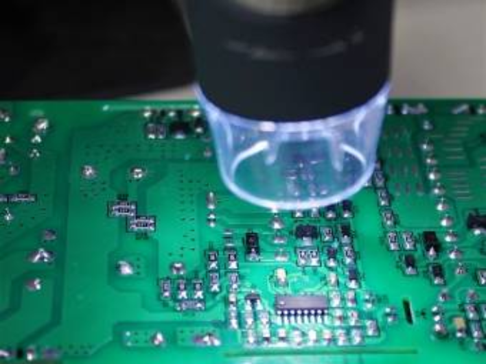
AI-Based PCB Component Identification
ASI Engineering uses custom imaging tools to automatically identify and classify all mounted components on a PCB. This includes ICs, resistors, capacitors, transistors, and other discrete parts typically found in control units, infotainment systems, and power modules.
These assemblies are increasingly common across EVs, hybrids, and connected vehicles—making automated identification essential for large-scale teardown and competitor cost benchmarking programs.
The captured image is processed through in-house vision algorithms to extract part identity, quantity, and placement. Each component is matched to the xcPROC database and used to auto-fill the electronic BOM inside xcPEP, our cost analysis platform. This reduces manual effort and ensures fast, scalable costing of automotive electronic assemblies.
Bounding Box Dimension Capture System
For physical components such as castings, molded housings, cross members, and interior modules, ASI uses a laser-based scanner to capture actual length, width, and height in seconds. These bounding box dimensions are fed directly into xcPEP to drive calculations related to material volume, blank size, packaging density, and shipping layout.
This data is critical in automotive programs where packaging space, material usage, and logistics efficiency are all tied to cost. It ensures every model reflects true physical parameters, not nominal drawings or estimates.
Automated Projected Area Capture System
Stamped, molded, or coated parts—like door trims, instrument panels, heat shields, or liftgate inners—are scanned using a calibrated imaging system that extracts the true projected surface area. This area data is passed into xcPEP and used to calculate press tonnage, paint consumption, plating cost, or heat treatment exposure.
In automotive should costing, projected area directly influences many process costs. Capturing it through imaging avoids drawing dependency and ensures consistent logic across large BOMs.
Use Cases
Internal Cost Lab Setup for a Global Passenger Vehicle OEM
xcPEP was deployed to establish a full-fledged internal should-costing lab for a leading global passenger car manufacturer. ASI Engineering configured structured BOM templates, regional input rates, and process libraries aligned to the OEM’s vehicle platforms and sourcing geographies. The client’s cost engineering team was trained to perform detailed part-level costing across use cases such as new vehicle development, supplier quote validation, and competitive teardown benchmarking.
The OEM now runs the cost lab independently, using xcPEP as the core platform, with ASI providing ongoing support and database updates as needed.
Should-Costing for New Part Development
ASI Engineering used xcPEP to perform early should costing for a commercial truck OEM during the development of multiple chassis and drivetrain components. The team-built cost models directly from early CAD and 2D drawings, capturing parameters such as material grade, section thickness, machining allowance, and process selection based on real manufacturing logic.
xcPEP was configured with sourcing assumptions pulled from xcPROC, including machine hour rates, labour inputs, raw material pricing, and tooling recovery estimates for the target region. As the designs evolved, the models were updated to reflect each iteration—allowing engineering, sourcing, and finance teams to align on cost expectations before RFQs were released. This helped the OEM establish realistic target costs early in the development cycle and supported informed supplier discussions with data-backed cost references.
Fact Packs for Supplier Negotiations
ASI Engineering used xcPEP to prepare structured fact packs for a two-wheeler OEM during a supplier negotiation cycle involving frame and body panel components. Each model was built using teardown data, drawing dimensions, and validated process logic. Parameters such as material usage, forming operations, welding cycles, paint coverage, and tooling assumptions were captured in detail.
Cost breakdowns were generated inside xcPEP, covering raw material, machine time, labour effort, overhead, and tool cost recovery. These were packaged into fact packs that provided sourcing teams with line-by-line visibility into cost drivers and regional rate assumptions.
The fact packs were used to challenge supplier quotes, support alternate sourcing discussions, and justify cost targets with defensible inputs—resulting in more transparent and data-driven negotiations.
Product Studies
Automotive cost engineering studies executed by ASI Engineering
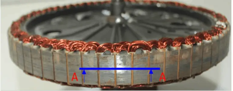
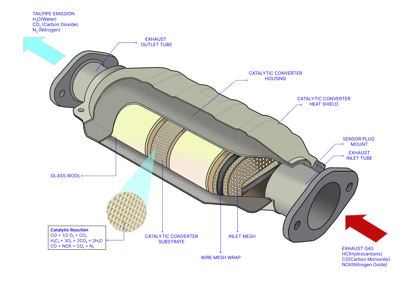
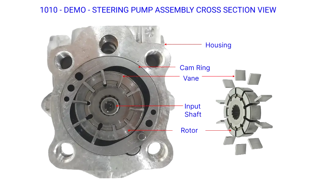
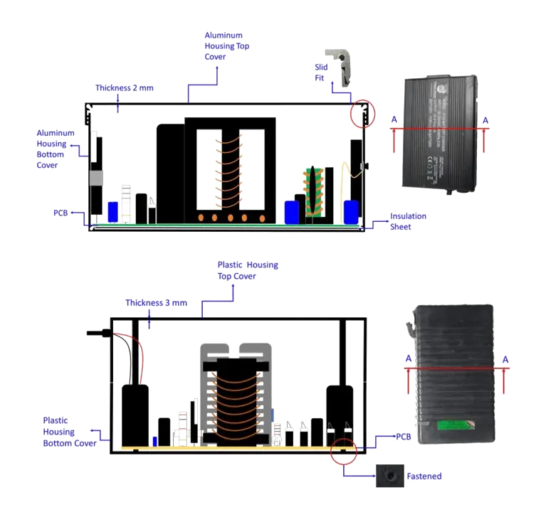
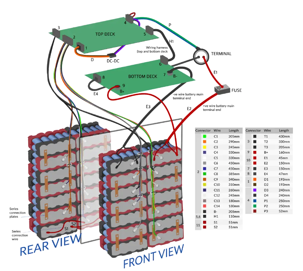
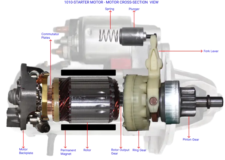
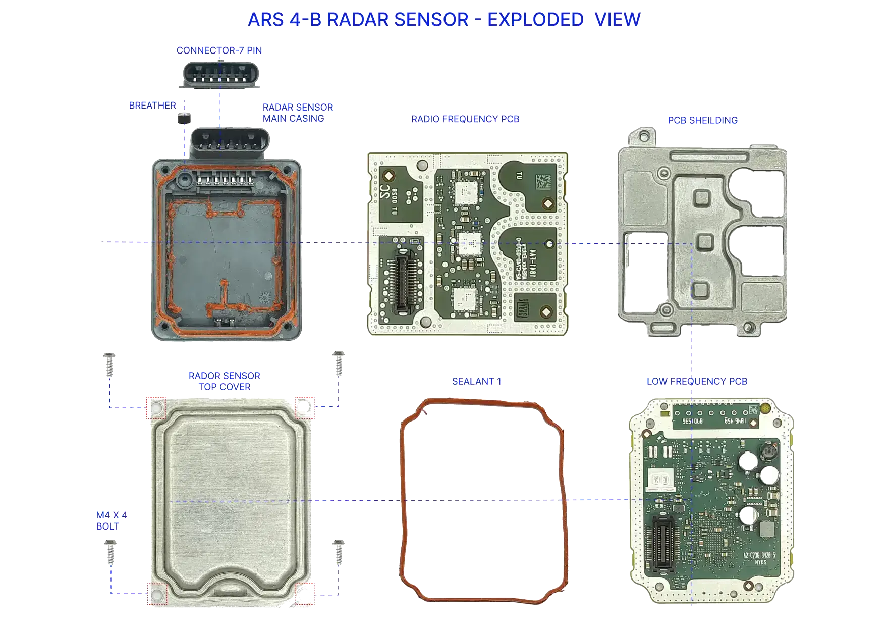
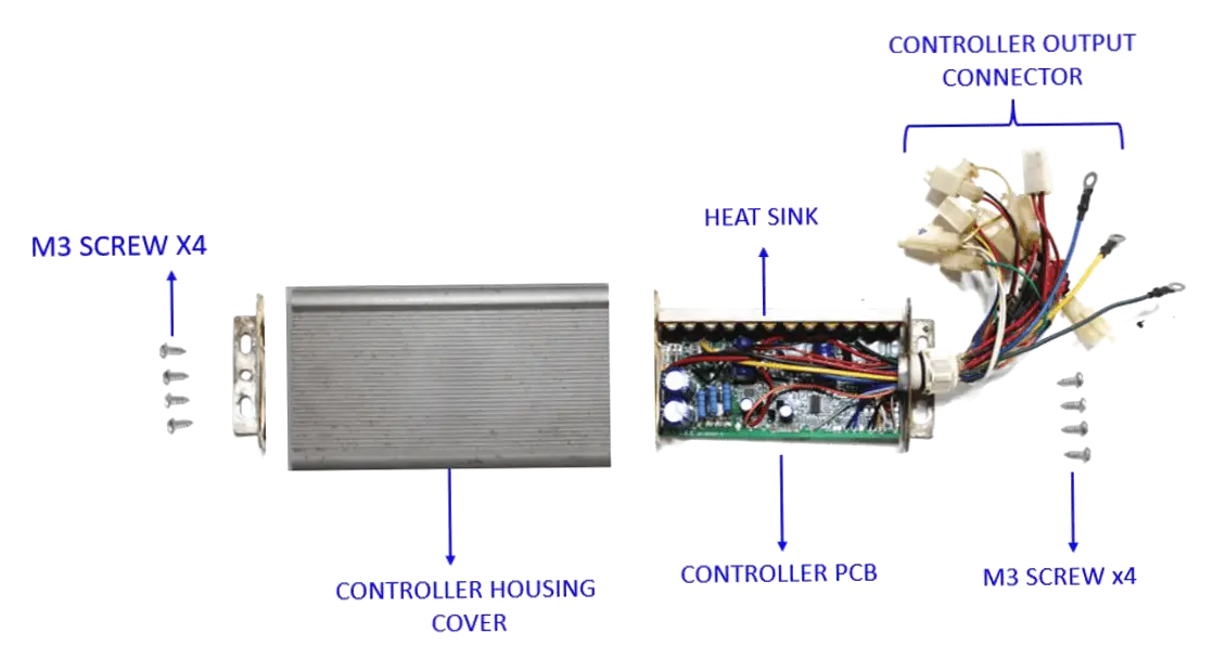
This section features selected teardown and costing studies conducted internally by the ASI Engineering team. Every image, model, and analysis shown here is built independently by ASI and reflects real-world automotive manufacturing practices.
The studies span a variety of systems including EV motors, mechanical subassemblies, plastics, castings, and electrical components used in two wheelers, passenger vehicles, and commercial platforms. Each example demonstrates how structured inputs and detailed process logic are used to create cost models that are both transparent and production-representative.
