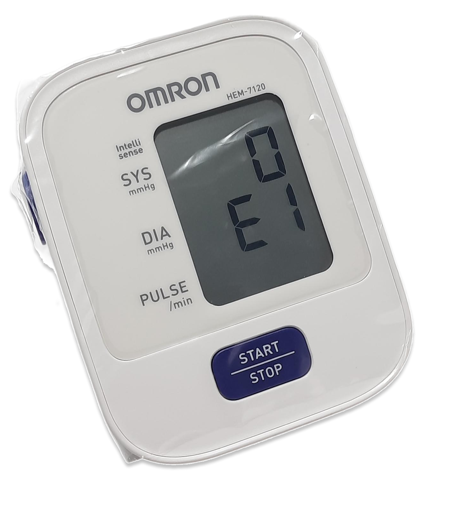
Omron BP Monitoring Device HEM-7120 Teardown, BOM and Should Costing
Disclaimer
This study was conducted entirely in-house by ASI Engineering to demonstrate the capabilities of the xcPEP® platform. The product was independently procured by ASI. No proprietary or confidential information from any other party has been used. Results are not updated after publishing.
Software platforms used for this study
This study is powered by ASI’s proprietary should-costing ecosystem - xcPEP and xcPROC - engineered to deliver real-world accurate, traceable should-costing across mechanical, electrical, and electronics components..

xcPEP delivers real-world accurate, transparent & defensible should cost analysis of mechanical, electrical & electronics components from drawings or physical parts.
Explore xcPEP →
xcPROC is the centralized database engine powering xcPEP. Built entirely by ASI’s data research team, each database is meticulously curated to be region-specific and time-specific.
Explore xcPROC →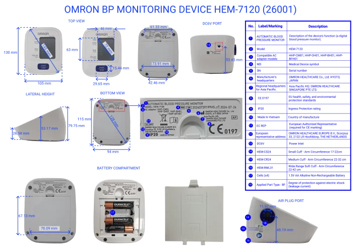
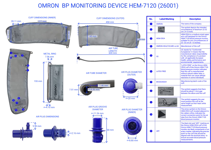
Prominent Features of Blood Pressure Monitoring Device
A comprehensive teardown and benchmarking of the blood pressure monitoring device was conducted, analyzing 35 features, specifications, and product-level details. Highlighted below are some of the standout features:
This compact device offers one-touch, fully automatic operation using oscillometric measurement for blood pressure and pulse readings. It features electronic inflation/deflation, dual power modes (battery/AC), an LCD display, memory storage, and built-in error detection—ideal for home, clinic, or outreach use.
Operation Type:
Fully automatic with one-touch start and stopPower Source:
Dual-mode: Operates on 4×AA batteries or via AC adapterMeasurement Range – Pressure:
0 to 299 mmHgMeasurement Method:
Oscillometric method for non-invasive blood pressure detection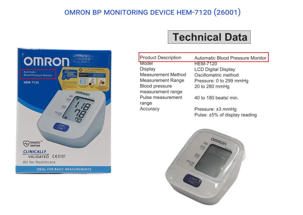
Error Indicators in the Automatic Blood Pressure Measurement Device
The device features 11 LCD error indicators to alert users of issues like cuff misplacement, movement, irregular heartbeat, or low battery, ensuring accurate and reliable readings.
Below are some of the key error indicators displayed by the device:
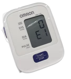
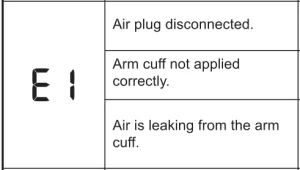
E1 Error: Inflating Error
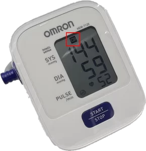
Irregular Heartbeat Indicator

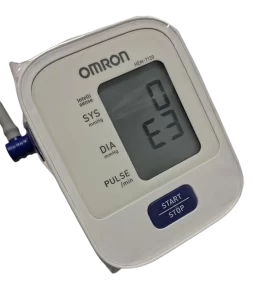
E3 Error: Cuff Inflation Issue

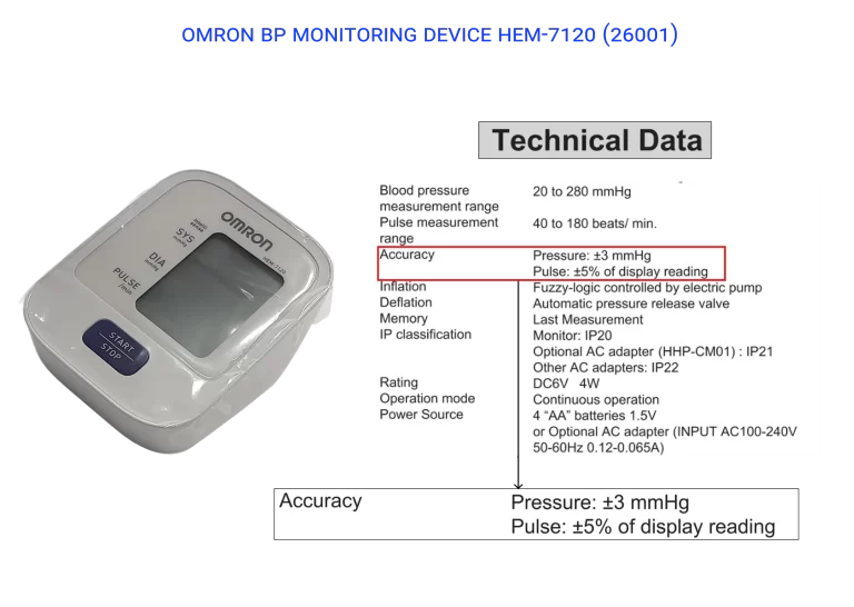
Measurement Accuracy of Automatic Blood Pressure Measurement Device
The device offers clinically reliable measurement accuracy, with a pressure tolerance of ±3 mmHg and pulse rate accuracy within ±5% of the displayed reading. This ensures consistent and dependable results for home and clinical use alike.
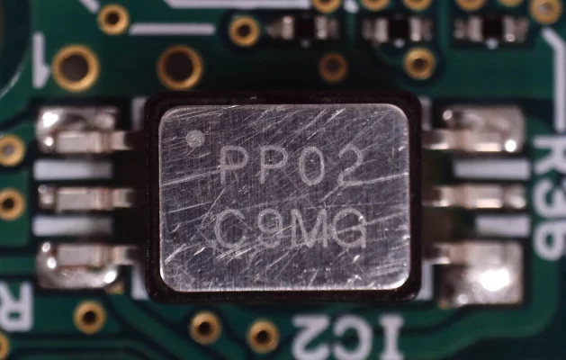
Piezoresistive Sensor Used in the Automatic Blood Pressure Measurement Device
- 0.1" male tube port
- Analog output range of 0–31 mV
- Vented gauge design
- Small 6-SMD module footprint
Working Principle:
- The sensor contains a flexible diaphragm integrated with a piezoresistive material.
- As the diaphragm deforms under pressure, the resistance of the embedded material changes.
- This resistance change is converted to a low-voltage analog signal proportional to the applied pressure.
- The signal is then digitized and processed by the microcontroller.
Microcontroller Used in the Automatic Blood Pressure Measurement Device
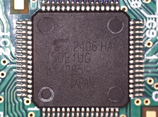
Powering the core functions of the device is Toshiba’s TMPM332FWUG(C) microcontroller, based on the ARM Cortex-M3 architecture.
- Flash Memory: 128 KB
- SRAM: 8 KB
It processes pressure sensor data, drives the LCD interface, and manages user interactions—all while supporting low-power operation suitable for portable medical use.
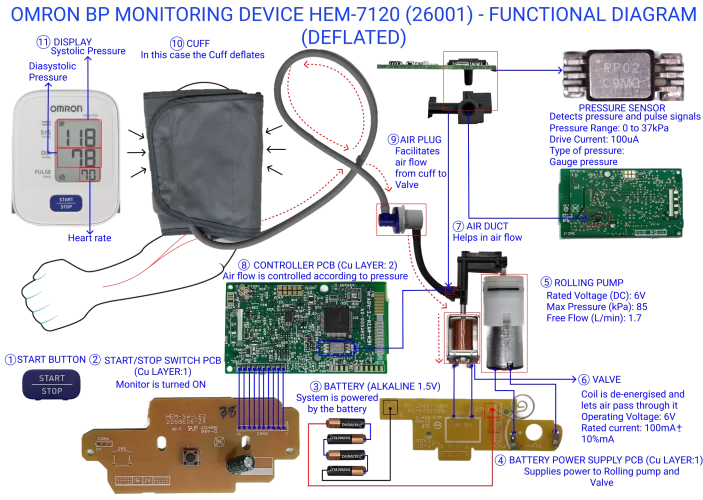
Functioning of Automatic Blood Pressure Measurement Device
Cuff Inflation – Pressurization Phase

- START Button Pressed (①):
The user presses the Start/Stop button, sending a signal through the Start/Stop Switch PCB(②) to the controller.
- Power Supplied (③ & ④):
The 1.5V alkaline batteries supply power via the Battery Power Supply PCB, energizing key components — the Rolling Pump, Valve, and Controller PCB.
- Valve Remains Closed (⑥):
During inflation, the Solenoid Valve is energized, keeping it closed to prevent air from escaping.
- The valve coil is powered (6V), which pulls a plunger inside the valve to block the air outlet.
- This ensures all air from the pump is directed only to the cuff, not vented out.
- Pump Starts (⑤):
The Rolling Pump begins pushing air through the connected tubing system.
- Air Routed via Duct and Plug (⑦ & ⑨):
The air travels through the Air Duct and Air Plug, inflating the Cuff wrapped around the user’s upper arm.
- Pressure Monitoring Begins (Sensor):
The 2SMPP-02 Piezoresistive Pressure Sensor continuously monitors the cuff pressure.
- It detects changes in pressure by deforming under mechanical force, altering electrical resistance.
- This change is converted to an analog voltage proportional to the cuff pressure.
- Signal Processing by Controller PCB (⑧):
The sensor’s analog voltage is sent to the Toshiba ARM Cortex-M3 microcontroller on the Controller PCB.
- It digitizes the signal, compares it with the programmed threshold.
- It adjusts pump operation accordingly.
- Inflation Stops at Target Pressure:
The pump continues until the pressure exceeds a pre-set systolic threshold (e.g., ~180 mmHg), after which the controller stops the pump while keeping the valve closed.
- Fallback Mechanism – Additional Inflation if Needed:
If the preset target pressure does not fully occlude the artery, and pulsations are still detected, the controller resumes inflation in small increments.The pressure continues rising until:
- Arterial blood flow stops completely (no oscillation detected), or
- The device hits the maximum safe pressure limit (typically around 280–300 mmHg).
Cuff Deflation – Depressurization Phase
- Valve Controlled Deflation Begins:
Once the target inflation pressure is reached, the air pump is turned off, and the electronic control valve is partially opened to allow gradual, controlled deflation of the cuff.
- Pressure Sensor Activation:
As air pressure slowly drops, the 2SMPP-02 piezoresistive pressure sensor continuously monitors the internal cuff pressure. This sensor detects subtle pressure fluctuations caused by blood flow restarting in the brachial artery.
- Oscillation Detection by Microcontroller:
The TMPM332FWUG(C) microcontroller analyzes the pressure signal for oscillometric waveforms. These waveforms indicate the return of pulsatile blood flow and are used to compute:
- Systolic pressure (beginning of oscillations),
- Mean Arterial Pressure (MAP) (peak oscillations), and
- Diastolic pressure (disappearance of oscillations).
- Valve Maintains Steady Deflation Rate:
The valve is controlled to ensure air exits at a steady rate (~2–5 mmHg/sec). This stability is important for waveform detection and signal analysis.
- Measurement Completion:
Once the oscillations diminish (below diastolic), the microcontroller finalizes the readings and saves the data for display.
- Valve Fully Opens – Complete Deflation:
After measurement is complete, the valve is fully opened, allowing the cuff to rapidly deflate and return to atmospheric pressure. This improves user comfort and resets the system.
- Valve Fully Opens – Complete Deflation:
After measurement is complete, the valve is fully opened, allowing the cuff to rapidly deflate and return to atmospheric pressure. This improves user comfort and resets the system.
- Triggers an error code,
- Terminates deflation or may attempt re-inflation, depending on firmware logic.
- Prompts the user to reattempt the measurement under better conditions.
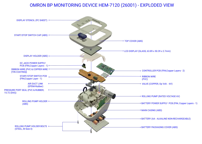
Bill of Materials (BOM) – Omron HEM-7120 Automatic Blood Pressure Monitoring Device
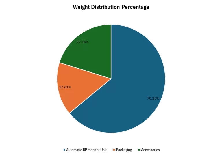
Weight Distribution – Automatic Blood Pressure Monitoring Device
To assess the composition of the device, we conducted a teardown-based analysis of the weight contribution across its key assemblies, including the core monitoring unit, accessories, and packaging.
Assembly-wise Weight Breakdown
- Core Monitoring Unit (incl. cuff):
- Heaviest component at 70.25% of total weight
- Accessories:
- Contribute 22.14% of total weight
- Packaging:
- Accounts for 17.31%, ensuring protection during transit

Manufacturing Category Distribution Analysis – Automatic Blood Pressure Monitoring Device

- Mechanical Bought-Out Parts (BOP): 56.1% – Major structural elements.
- Electronic Bought-Out Parts: 10.6% – Includes key electronic modules.
- Injection Moulding Parts: 7.6% – Used for casing and functional plastics.
- PCBs, Wiring, Display: Highlight electronic control and UI integration.
- Other Materials: Includes fabricated steel, rubber, fabric, film, and paper – ensuring durability, comfort, and safe packaging.
Automatic Blood Pressure Monitoring Device Multi-level BOM (Bill of Materials) Structure
Following the teardown, a Multi-level BOM (Bill of Materials) structure was created to map out the device’s primary assemblies, their sub-assemblies, and the individual components within. This structured breakdown allows for a detailed understanding of the device's design, material usage, and operational flow — enabling targeted analysis of functionality, manufacturing processes, and potential cost drivers.
The Automatic Blood Pressure Monitoring Device consists of 56 parts in total, distributed across three key subsystems as shown below:

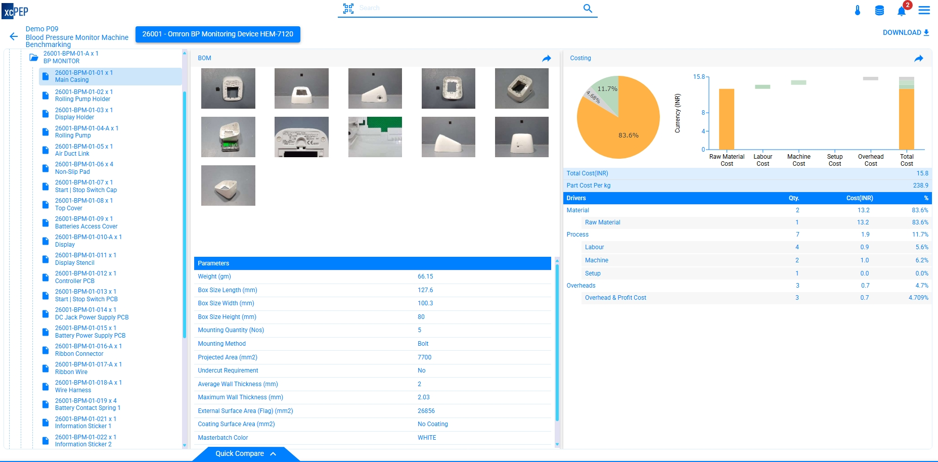
Automatic Blood Pressure Monitor Teardown and Detailed BOM (Bill of Materials) Analysis
Assemblies & Components – The Omron HEM-7120 comprises 3 main assemblies and 56 components.
BOM Parameters – A total of 30 key BOM attributes were tracked, covering size, weight, material type, electrical/mechanical function, and integration method. Given the simpler construction, the average parameters per part were about 14.
PCB Details of Automatic Blood Pressure Monitoring Device
Controller PCB in Automatic Blood Pressure Monitoring Device
The Controller PCB serves as the device’s central unit, featuring Omron’s 2SMPP-02 pressure sensor for measurement and Toshiba’s TMPM332FWUG(C) microcontroller for data processing, motor control, and display management. It is the most complex and cost-intensive PCB in the device.
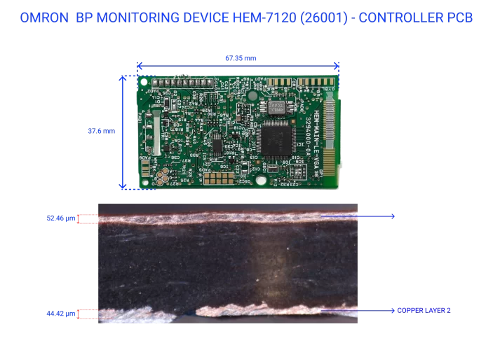
Start | Stop Switch PCB in Automatic Blood Pressure Monitoring Device
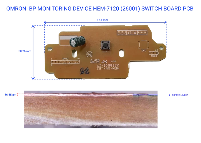
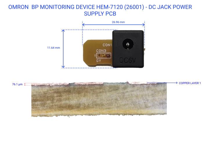
DC Jack Power PCB in Automatic Blood Pressure Monitoring Device
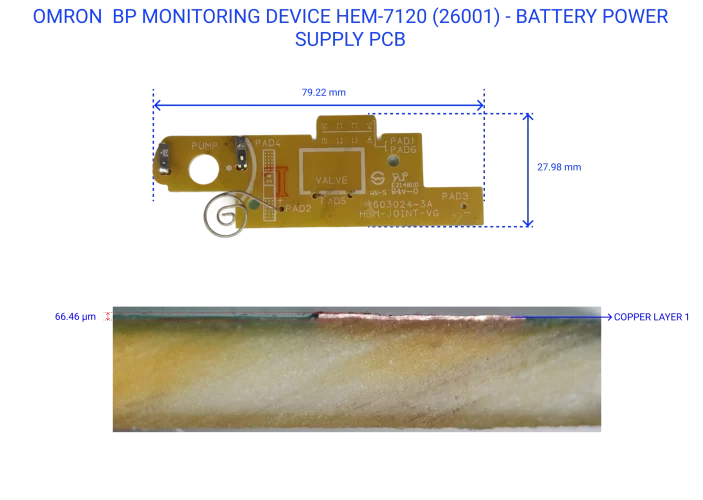
Battery Power Supply PCB in Automatic Blood Pressure Monitoring Device
The Battery Power Supply PCB provides connectivity and routing for battery-powered operation. Though it contains no active electronic components, its function is critical for supplying power to the valve and pump system during standalone use. The teardownconfirmed its importance in enabling mobile operation and ensuring reliable power distribution.
Should Cost Analysis of Automatic Blood Pressure Monitoring Device
Detailed Should Costing Breakdown of Automatic Blood Pressure Monitoring Device
- The device was manufactured in Chennai, Tamil Nadu.
- The should-costing model assumes an annual production volume of 12,00,000 units.
- All costing estimates are based on Q1 FY25–26 material prices and labor benchmarks.
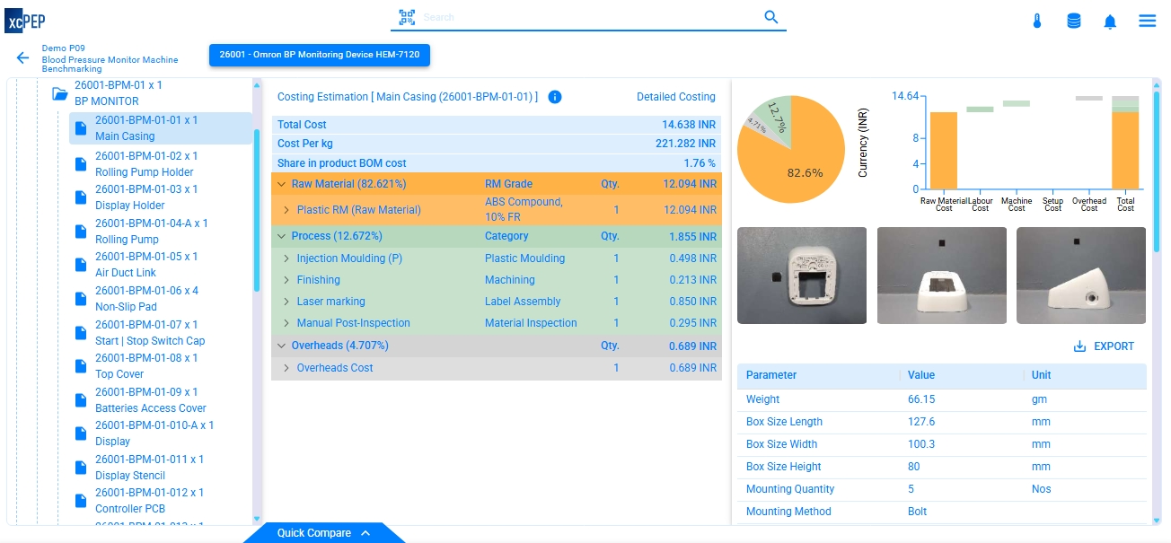
The breakdown below provides insights into the major cost drivers in accessories, packaging, and the blood pressure machine.
Accessories Cost Contribution Analysis of the Blood Pressure Monitoring Device


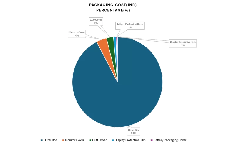
Packaging Cost Contribution Analysis of the Blood Pressure Monitoring Device

Cost Contribution in BP Monitor Machine
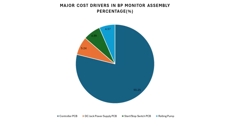
The BP monitor machine assembly carries a total should-cost of ₹775.73. The should-costing analysis identifies the following components as the most significant cost drivers within the fully assembled unit:

PCB Cost Contribution Analysis of the Automatic Blood Pressure Monitoring Device
The should-cost of all PCBs used in the Automatic Blood Pressure Monitoring Device amounts to ₹530.86. Below is the cost distribution among the different PCBs:

Final Should-Cost Summary and Key Insights for Automatic Blood Pressure Monitoring Device
Key Observations from the Should-Costing Analysis
The should-cost of all PCBs used in the device is ₹530.86, accounting for 61.95% of the overall should-cost, making them the most critical cost drivers.
The Controller PCB alone contributes ₹428.61, representing 50.2% of the total should-cost. This is driven by high-value components such as the microcontroller and pressure sensor, positioning it as the top target for design and sourcing optimization.
The BP monitor machine assembly holds a total should-cost of ₹775.73. Within this, key contributors are:
- Controller PCB – ₹428.61 (55.25%)
- DC Jack Power Supply PCB – ₹40.68 (5.24%)
- Start/Stop Switch PCB – ₹38.68 (4.99%)
- Rolling Pump – ₹35.43 (4.57%)
These four elements alone contribute over 70% of the machine assembly's should-cost, emphasizing their importance in any cost-reduction efforts.
The remaining PCBs — Battery Power Supply PCB and others — collectively amount to ₹24.71 and are well-optimized for cost, contributing only marginally to the total should-cost.
Accessories add ₹66.37 to the device should-cost, with the battery making up nearly 90% of that total. These components are essential and offer limited scope for savings.
Packaging components contribute an additional ₹14.72, with the outer box alone accounting for over 92% of the packaging should-cost.

