Continental ARS 4-B Radar Sensor Teardown & Cost Analysis
L3 physical teardown, BOM extraction, and should-cost analysis of the 77GHz FMCW Radar powering Level 2 ADAS in Tesla Model 3 and Mercedes Benz E-Class.
A comprehensive L3 physical teardown and should-cost analysis of the Continental ARS 4-B 77GHz FMCW Radar Sensor - a core ADAS component in the Tesla Model 3 and Mercedes-Benz E-Class.
To establish a defensible should-cost baseline for procurement negotiations, identify cost reduction opportunities, and benchmark manufacturing against industry best practices.
Mid-range 77GHz FMCW radar for adaptive cruise control, emergency braking, and object detection. 170m range, 45 azimuth, 9 major sub-assemblies.
Complete BOM (70+ parts, 18 params each), 12 engineering schematics, EDAX/FTIR material verification, and a zero-based should-cost model on regional data.
01Executive Overview
With the advent of advanced safety features like Adaptive Cruise Control, Emergency Brake Assist, and Forward Collision Warning, the need for Continental ARS 4-B Radar Sensor in cars is increasingly necessary.
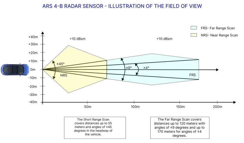
The Continental ARS 4-B radar sensor is used in a range of vehicles, including Tesla Model 3 & Mercedes Benz E Class. This sensor is mounted to the front center of the car behind the bumper, providing critical data to the car's safety systems. It covers short-range (55m at 45) and far-range scans (120m at 9, 170m at 4), operating at 7677GHz.
The sensor utilises FMCW (Frequency Modulated Continuous Wave) technology with rapid ramps to measure distance and velocity of objects without reflectors. This measurement is achieved in a single cycle, utilizing Doppler's principle at a scanning rate of 15 scans per second. It is capable of measuring relative velocities between -400 and +200 km/h.
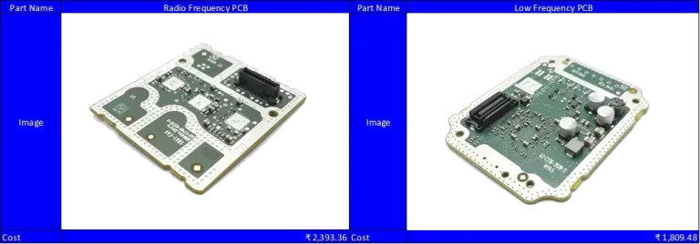
The RF Printed Circuit Board (PCB) incorporates the antenna, whereas the Low Frequency (LF) PCB contains the signal processing unit, power supply, and CAN interface. Data is generated every 60 milliseconds, providing real-time feedback for ADAS decision-making. The sensor separates receive and transmit antenna arrays to enable advanced digital beamforming techniques.
02Features & Operations
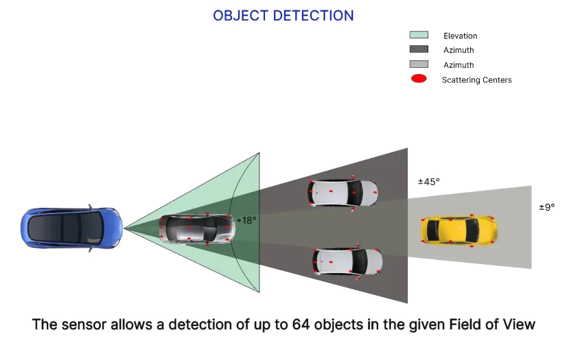
Detects up to 64 objects concurrently, identifying multiple scattering centres per object to construct an accurate environmental model.
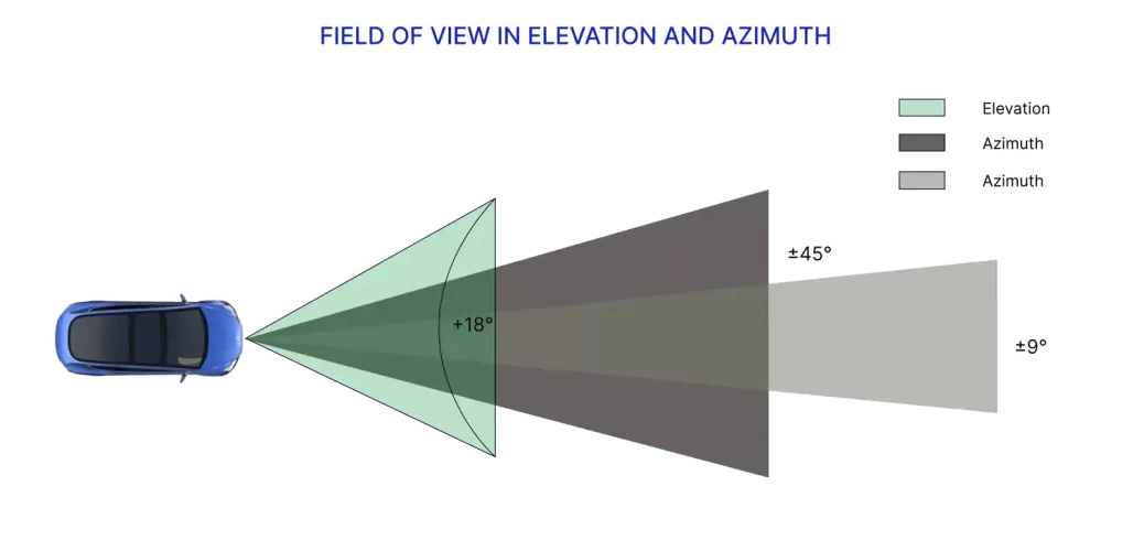
1. Field of View in Azimuth & Elevation
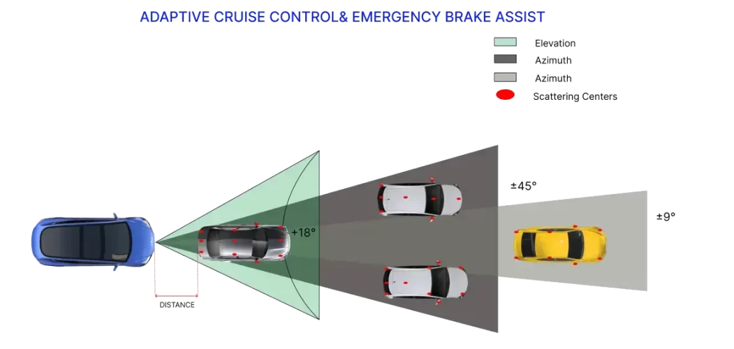
The Continental ARS 4-B Radar sensor has a wide field of view both in azimuth and elevation. In azimuth the sensor can scan objects up to 45 (short range mode at 55m) and 9 (long range at 120m) and 4 (far range mode at 170m) as shown in Figure 1.3 and Figure 1.4.
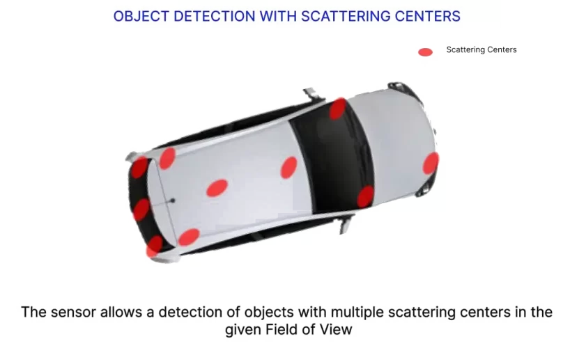
2. Object Detection
The radar sensor can detect up to 64 objects simultaneously within its field of view. Each object is represented by multiple scattering centres, allowing the sensor to construct a detailed 3D model of the environment.
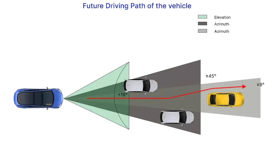
3. Future Driving Path
Once the Radar Sensor detects objects within its Field of View, it transmits a specific message output to the Future Driving Path system. The message contains the predicted path of the vehicle based on current trajectory and velocity data from detected objects.
4. Adaptive Cruise Control & Emergency Brake Assist
Adaptive Cruise Control: The sensor detects objects within its Field of View and transmits a targeted message output to the Adaptive Cruise Control (a driver-assistance system). The following messages are sent by the radar sensor:
- A message containing a list of all objects detected within the Field of View.
- A message containing the distances to the detected objects.
- If the distance to the vehicle ahead falls below the threshold distance, a Brake Request message is sent to the Adaptive Cruise Control system.
Emergency Brake Assist: Once the Radar Sensor detects objects within its Field of View, it sends a specific message output request to the Emergency Brake Assist system. The following messages are sent:
- A distance warning message is transmitted when the distance to one or more detected objects falls below a predetermined threshold.
- If the distance falls below a second threshold, a deceleration request message is transmitted.
- The braking system initiates deceleration to avoid a collision. The sensor provides the necessary deceleration information.
5. Occupant Safety Support
After detecting objects within its Field of View, the Radar Sensor sends a specific message output request to the Occupant Safety Support system. The following messages are transmitted:
- A safety belt pre-tensioning request message is sent in the event of a vehicle collision, which activates the safety belt to pull back the driver and front seat passenger to their seats before the impact occurs.
- An Airbag Prefill Request message is sent in the event of a vehicle collision, which activates the airbag.
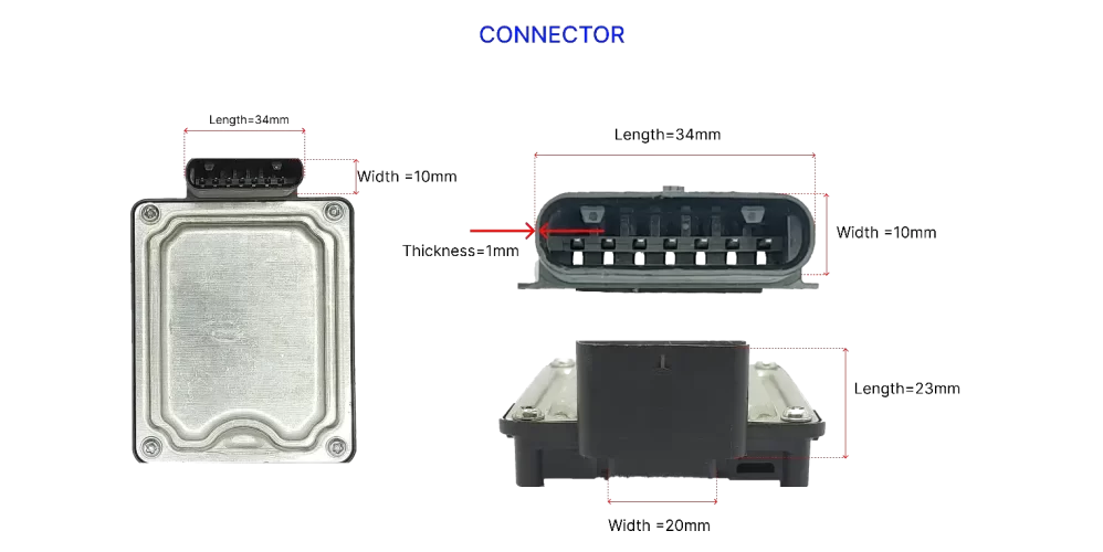
6. CAN Connector
The connector for the Continental ARS 4-B Radar Sensor Controller Area Network (CAN) contains seven terminals made of copper coated with tin. Although copper is commonly used for terminals due to its good electrical conductivity and affordability, it can corrode over time and result in poor connections. To avoid this, a layer of tin is often applied to the copper terminals to provide protection against oxidation.
Tin plating offers various advantages for CAN applications, such as better resistance to corrosion, improved solderability, and increased durability. Additionally, it helps to prevent the copper from oxidising, which ensures a dependable connection.
03System Architecture
In the field of radar sensor engineering, a thorough understanding of the packaging, overall construction, and functioning of the device is essential. An architecture study was conducted, resulting in the creation of 12 diagrams that comprehensively categorize the various aspects of the radar sensor:
- Packaging diagram - details the mounting of all parts and key dimensions
- Positioning diagram - explains how the sensor should be positioned onto the vehicle
- Layout diagram - depicts the PCBA layout
- Functional diagram - provides insight into the antenna functionality
Packaging Diagram
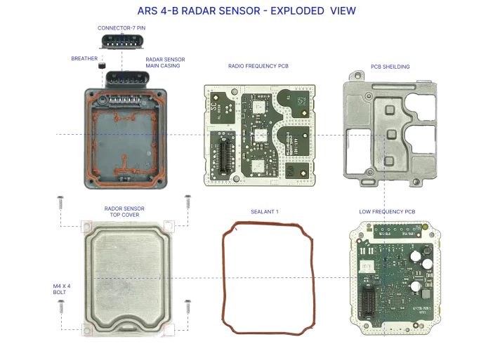
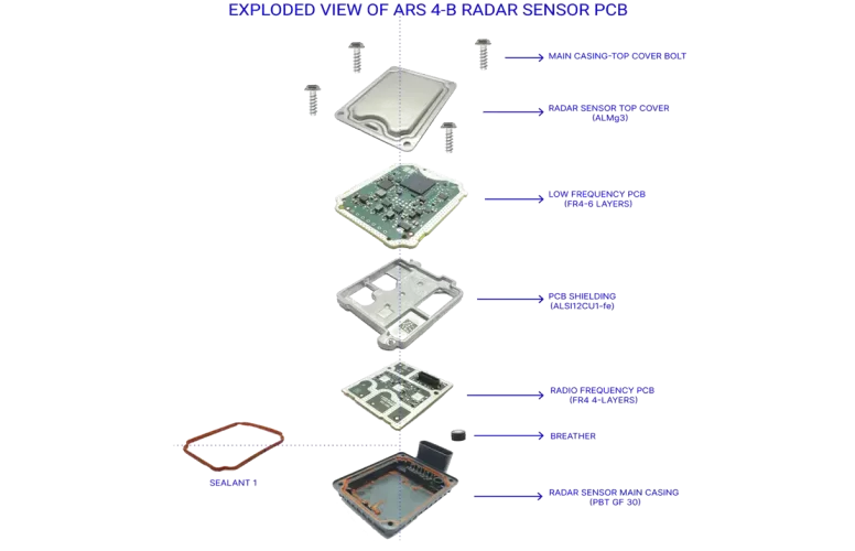
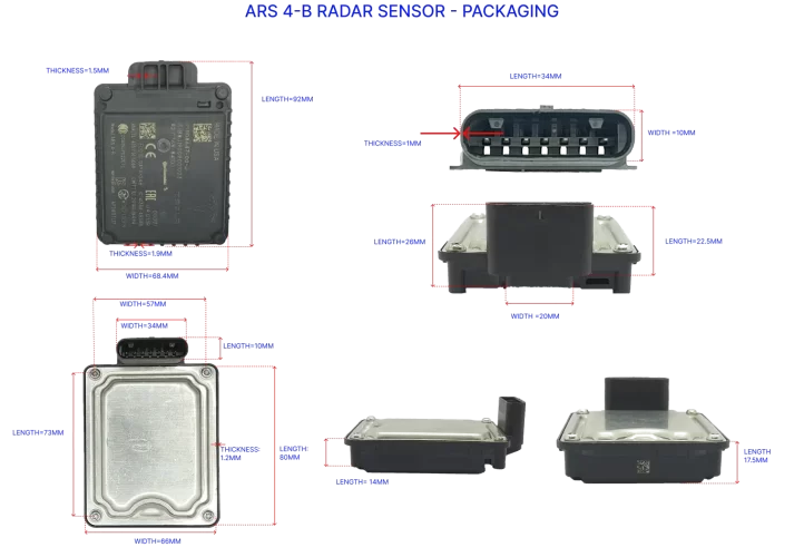
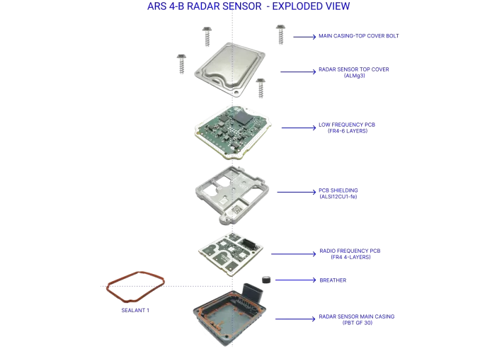
The Continental ARS 4-B radar sensor boasts a compact design with dimensions of 92mm in length, 68mm in width, and 30mm in height. It is comprised of two printed circuit boards (PCBs) the RF/antenna PCB and the LF PCB which are housed within a PBT material casing reinforced with 30% glass fiber and separated by an aluminum shield. The PCBs are securely enclosed with an aluminum cover that utilizes a silicon-based seal, fastened with four M4 5 Star configuration Torx screws. To prevent overheating, a breather/vent is provided with a filter to restrict dirt entry into the sensor.
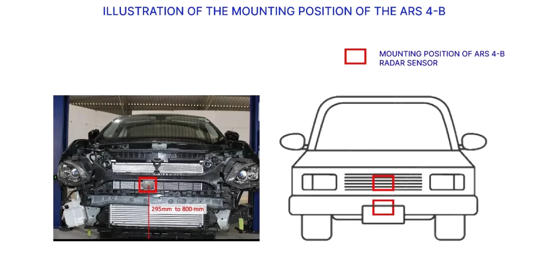
Positioning
The positioning diagram depicts the mounting location of the Continental ARS 4-B radar sensor relative to the road surface level. The sensor is mounted in a vertical orientation at a height ranging from 295mm to 800mm above the road surface level. It is situated in front of the vehicle and behind the bumper. Additionally, the sensor is mounted at a 0 angle relative to the driving direction of the vehicle.
04PCB & Antenna Design
Layout Diagrams
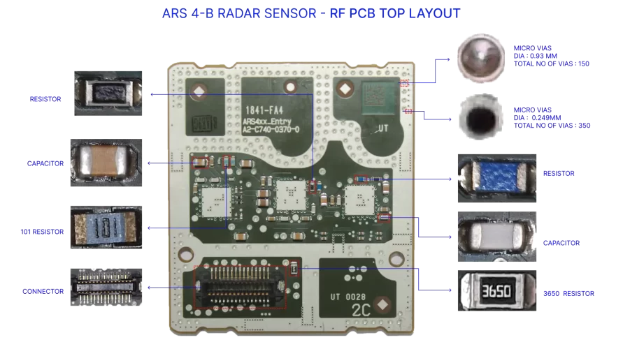
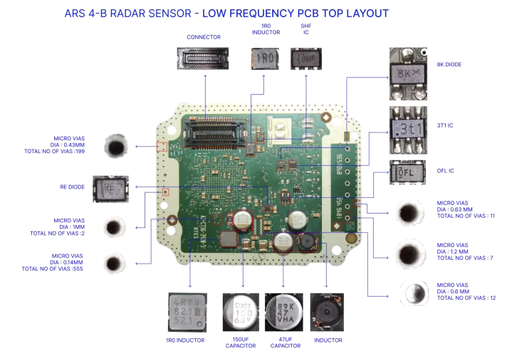
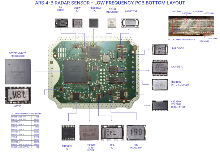
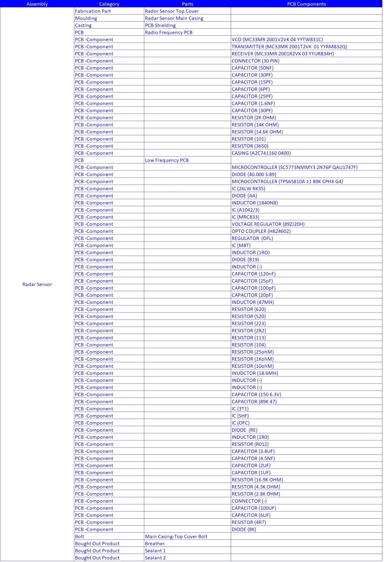
There are two printed circuit boards (PCBs) containing approximately 70 electronic components, including a substrate and microstrip receiver and transmitter antennas. These components consist of 14 integrated circuits (ICs), 1 optocoupler, 5 diodes, 19 resistors, 8 inductors, 19 capacitors, and 2 connectors. The accompanying diagrams illustrate the component layout and their respective positions, along with specifications.
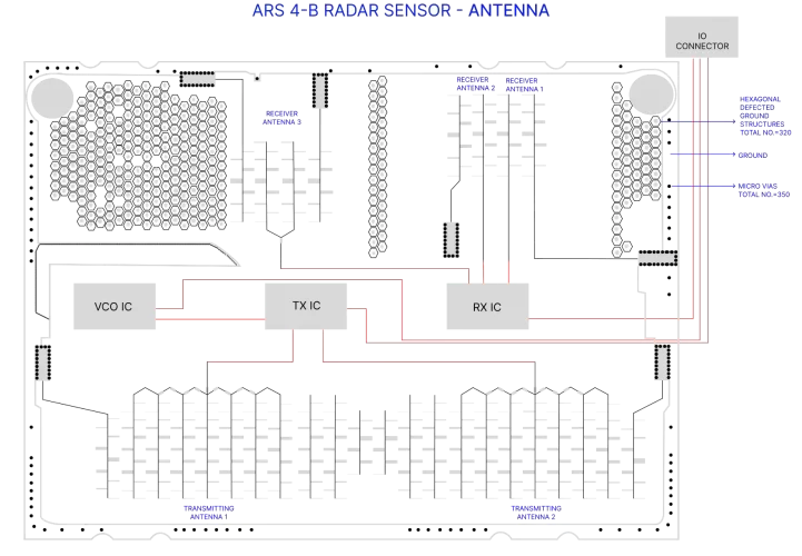
Antenna Functionality
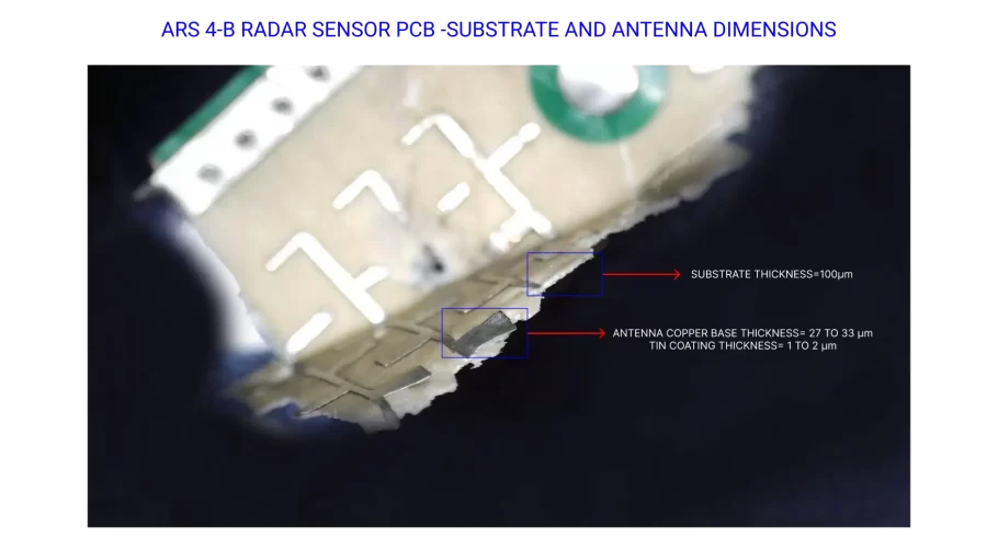
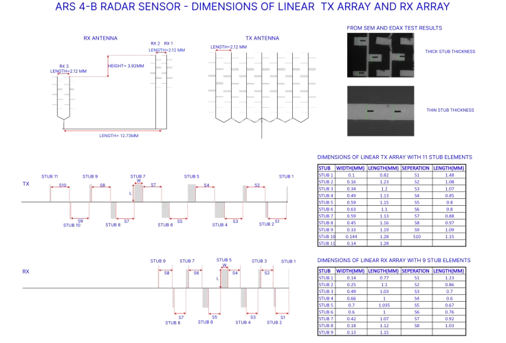
The Continental ARS 4-B sensor utilizes a series-fed microstrip patch antenna, with two transmitter (TX) and three receiver (RX) antennas printed on a PTFE (Teflon) substrate that is 100m thick in the RF PCB. By employing multiple-input multiple-output (MIMO) concepts and increasing the number of Tx and Rx antennas, higher angle resolution can be achieved. The conducted power is less than 10 dBm (10mW).
To enhance the bandwidth of the antenna, the thickness of the PTFE substrate is kept at 100 microns. Additionally, a resistive sheet is printed on top of the substrate and a metallic plane with via fences are used to mitigate surface waves. The different types of losses in an antenna include dielectric loss, conductor loss, and surface loss, which can be reduced by selecting appropriate materials during manufacturing.
Receiver
The RX1 and RX2 antennas are comprised of a single RX line array separated by a distance of 2.12 mm. The RX3 antenna is a small two-dimensional array consisting of two individual linear RX arrays separated by 2.12 mm. In the y direction, the RX3 array is separated by 3.92 mm from RX1 and RX2 antennas, while in the x direction, it is positioned 12.73 mm away from the midpoint between RX1 and RX2. Each RX line consists of nine stubs with different lengths and widths.
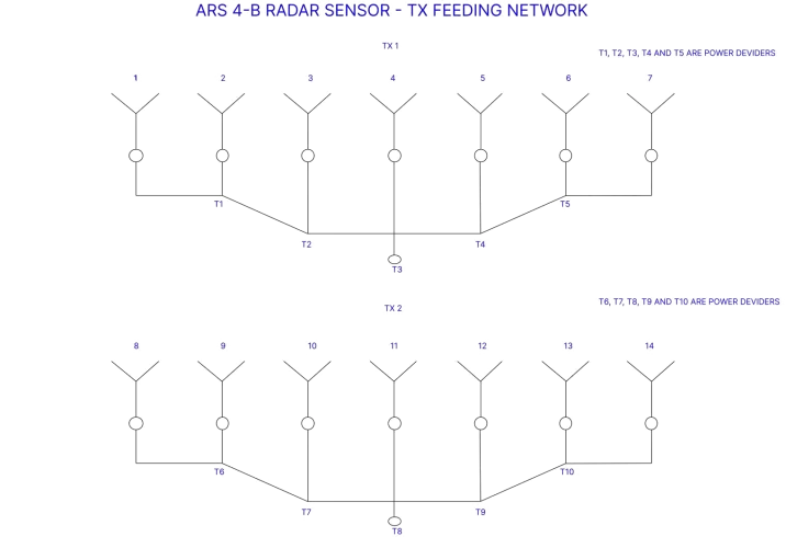
Transmitter
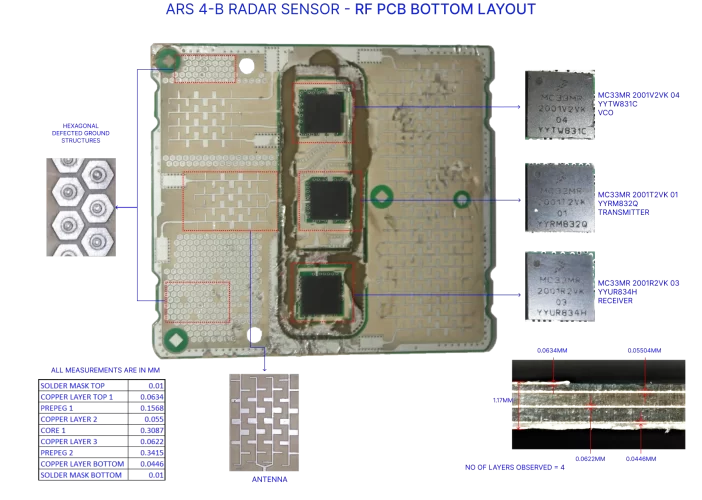
The TX antennas are divided into two sets, with each set comprising seven identical TX line arrays separated by a distance of 2.12 mm. All seven TX lines are connected to the feeding network. To split a common RF signal to the array antenna, five power dividers (T1T5) are utilized. Each TX line is comprised of eleven stubs with varying lengths and widths.
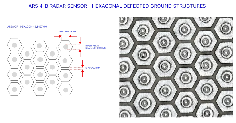
Hexagonal Ground Structures
The patch antenna is equipped with hexagonal defected structures and vias to minimise reflection. These structures are incorporated to enhance the impedance matching between the antenna and the transmission line or feed network, thereby reducing reflection. Additionally, the hexagonal structures impact the operating bandwidth and effectively reduce the substrate's dielectric constant.
The Hexagonal defected ground structures play a crucial role in distributing the current in the ground plane and regulating input impedance and excitation of radio waves in the substrate. This ensures a more uniform current distribution and leads to better radiation properties.
05EDAX Material Analysis
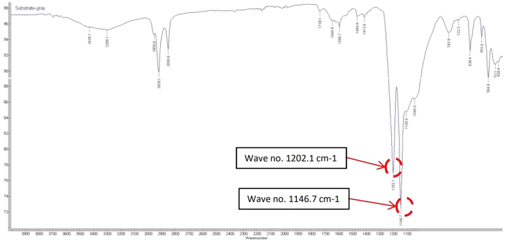
Substrate (FTIR Analysis)
The evaluation of antenna substrate materials was performed utilizing cutting-edge testing equipment in laboratory settings. Specifically, the Agilent Technologies Cary 660ATR Diamond, along with the Resolutions Pro FTIR software, was employed. The testing range spans from 4000 to 400 cm? and is geared towards transmittance measurements. Subsequently, the material underwent DSC analysis, where its melting point was identified at 317.5C. Through these two methods, it was concluded that the substrate material is PTFE (Polytetrafluoroethylene) with a dielectric constant of 2.1 and relative permittivity of 2.050.01.
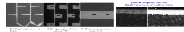
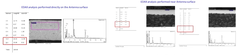
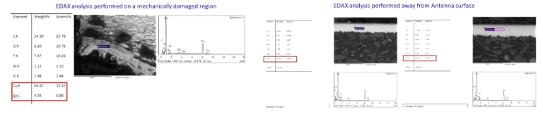
Microstrip Antenna (SEM/EDAX)
Testing of antenna material was carried out using the Zeiss EVO 18 Test Equipment, in compliance with ASTM F 1372:1993 for SEM examination and ASTM E 1508-12a:2019 for EDAX analysis. The antenna is composed of copper material with a protective tin coating layer. The antenna thickness at the thin track is approximately 126 microns, while it varies from 408 to 690 microns in the thick track. The tin coating thickness ranges between 1 to 2 microns, while the copper base thickness ranges from 27 to 33 microns.
06BOM & Cost Drivers
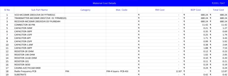
Bill of Material Study
Our team has performed a comprehensive last-level teardown analysis of the Continental ARS 4-B Radar Sensor. Through a bill of materials (BOM) study, we have systematically documented data pertaining to the various part attributes and analyzed this information to gain a detailed understanding of the device.
Each part or component has been thoroughly evaluated and an average of 18 parameters have been mapped per item, depending on the complexity category of the part.
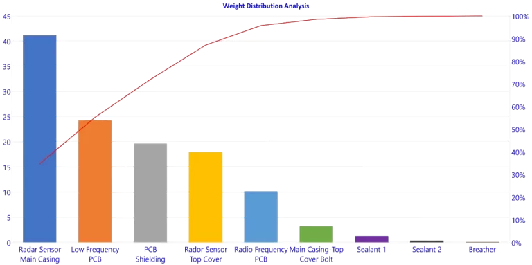
Weight Distribution Analysis
The total weight of the Continental ARS 4-B is 118.82g. The sensor's main casing weighs 41.15g (34.63% of total). The Low Frequency PCB accounts for 20.45%, the aluminum PCB shielding 16.57%, and the aluminum top cover at 18.01g. These four items account for 90% of the total weight.
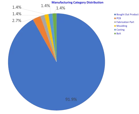
Manufacturing Category Distribution
The components of the Continental ARS 4-B Radar Sensor with different manufacturing categories are represented in the chart below. We have 74 bought out or off the shelf parts due to electronics child parts (resistors, capacitors, ICs, inductors etc.) used on the PCBs. Others are PCB Board, casing & shielding.
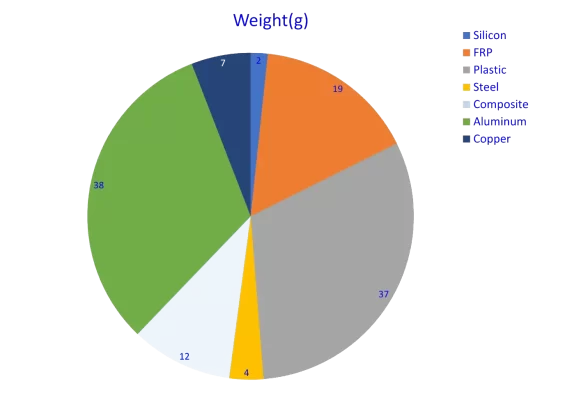
Raw Material Distribution
The Continental ARS 4-B radar Sensor is composed of various materials, with aluminum being the primary material for cover and shielding (38g). The casing material is plastic (37g). The RF and LF PCB boards contain FR-4 material content (19g).
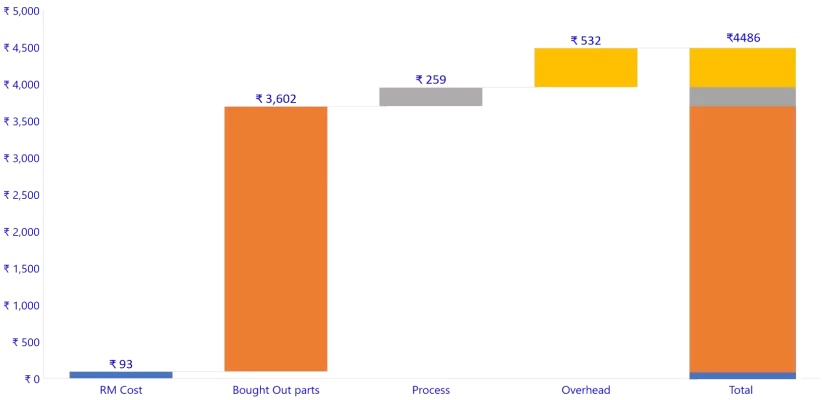
Should Cost Analysis of Continental ARS 4-B
A comprehensive should cost analysis analysis was conducted, resulting in a manufacturing cost of ?4,486 INR, taking into account:
- Production in Chennai, Tamil Nadu
- Annual volume of 240,000 units
- Latest material rates, labor hourly rates, and machine hour rates (Jan'23)
- PCB child parts considered as bought out in bulk from Digikey
- Indian Rupees (INR) currency used for cost analysis
Outcome
Raw material accounts for 82% of the cost (?3,695). Value-add/process cost is ?259, and overhead costs amount to ?532.
Cost Driver Analysis
Cost Pareto
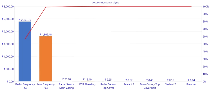
High Cost Items
Cost Analysis Reports
Table 1.2 - RF PCB Cost Analysis Report
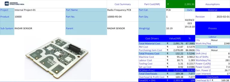
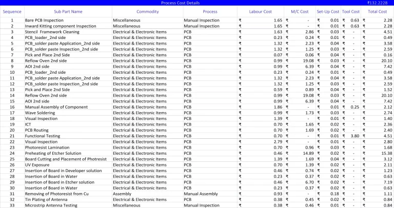
Raw material constitutes 82% of the absolute unit cost. The RF and Logic PCBs dictate the product's gross margins, making semiconductor and substrate sourcing the defining cost lever.
Software Platforms Used
Should Cost Software
xcPEP delivers real-world accurate, transparent and defensible should cost analysis of mechanical, electrical and electronics components from drawings or physical parts.
Explore xcPEP →Should CostData
xcPROC is the centralized database engine powering xcPEP. Each database is meticulously curated by a dedicated data research team to be region-specific and time-specific.
Explore xcPROC →