Starter Motor Teardown & Feature Study
VA/VE exercise on a gear-reduction starter motor for commercial vehicle application - featuring BOM extraction, architecture study, and feature mapping using xcPEP.
A comprehensive teardown and feature study of a gear-reduction starter motor used in commercial vehicle applications - mapping features, BOM, specifications, and architecture using xcPEP.
To conduct a VA/VE exercise mapping material information, architecture layout, manufacturing process complexity, and part-level features for benchmarking and design optimization.
Permanent magnet, gear-reduction type starter motor with planetary gear set for torque multiplication. Used in commercial vehicles with large flywheels requiring higher cranking torque.
Product & part-level features, technical specifications, complete BOM hierarchy from xcPEP, packaging & interface architecture diagrams, and exploded views.
01Executive Overview
A starter motor is an electric motor designed to initiate the operation of an internal combustion engine. The pinion gear meshes with the flywheel and rotates it when the key is turned ON, and disengages when the engine starts to run by itself.
Recently we conducted a VA/VE exercise on the starter motor used for commercial vehicle application. We at Advanced Structures India use Engineering Intelligence and xcPEP to map data which includes material information, architecture and layout study, manufacturing process and complexity data.
The motor considered in this activity is of gear reduction type where a planetary gear set is used for torque multiplication since the size of the flywheel is large and higher torque is required to rotate it. The starter motor is a permanent magnet armature type with permanent magnets acting as a stator to rotate the rotor made up of electromagnets.
Types of Starter Motors
Based on gear reduction methods:
- Direct Drive Electric Starter Motor
- Gear Reduction Type Starter Motor
Based on armature:
- Permanent Magnet armature type
- Field Coil armature type

This blog contains findings on starter motor consisting of: introduction and types, features and specifications mapped, BOM generated from xcPEP, and architecture and layout study.
02Product-Level Features
Product level features are data mapped by considering the product as a whole system. Features are mapped using the xcPEP tool. The features are divided into product level and part level categories.
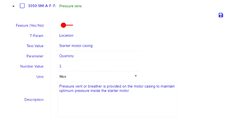
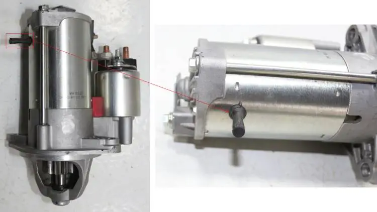
1. Breather or Pressure Vent
A breather made of rubber is present to regulate the pressure built-up inside the motor by releasing excess pressure to the atmosphere.
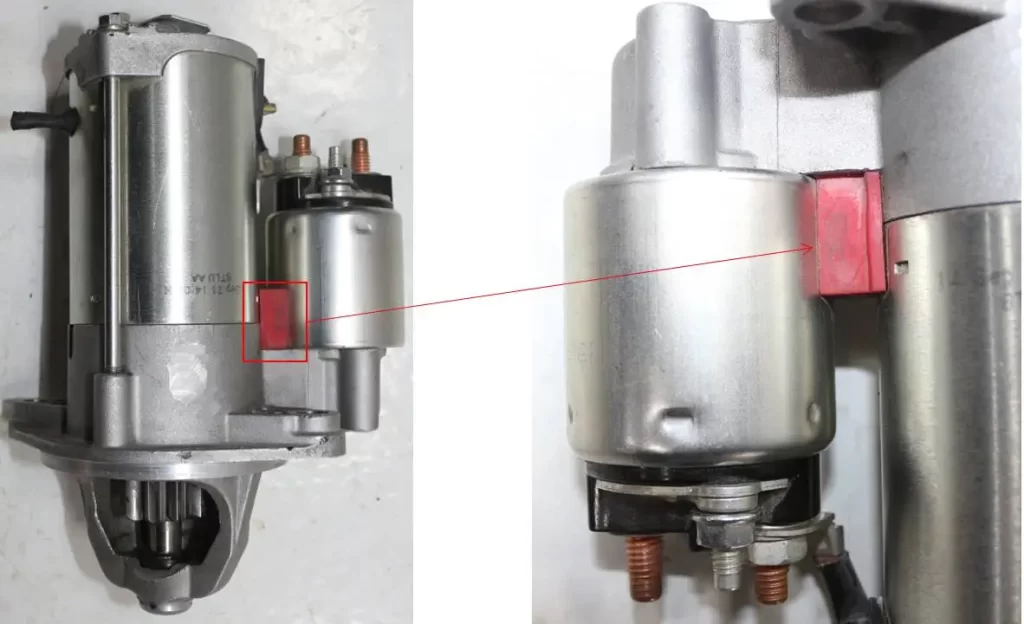
2. Damper Between Solenoid and Motor Casing
A rubber damper is used between the solenoid and motor casing to reduce transfer of vibrations from motor to solenoid during the meshing of pinion gear with flywheel.

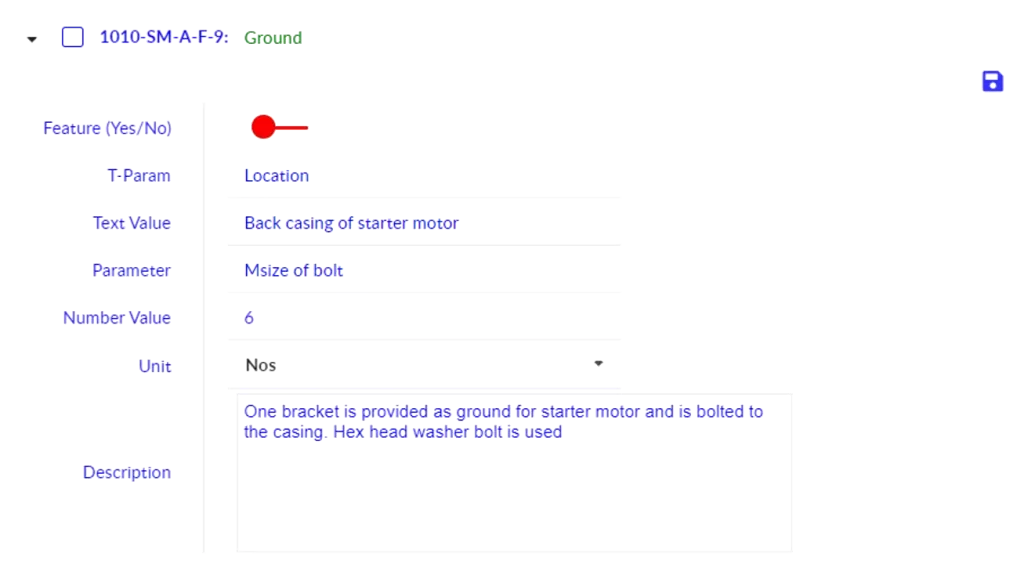
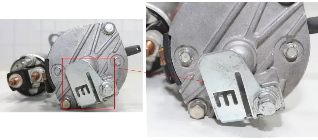
3. Ground Provision
A metal bracket acts as a ground for this starter motor, mounted to the backplate of the motor casing using an M6 hex head bolt and a washer.
03Part-Level Features
These features are mapped by considering individual parts of the starter motor as a separate system, providing a proper understanding of all individual parts present in the starter motor.
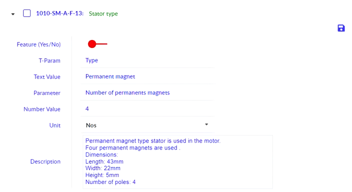
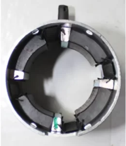
1. Stator Type
Four permanent magnets act as a stator and are glued and separated using clips inside the permanent magnet casing, which helps in rotating the rotor made up of electromagnets.
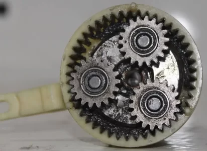
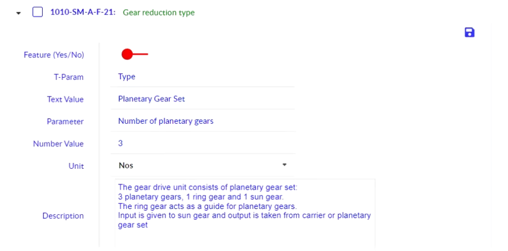
2. Gear Reduction Type
Commercial vehicles require a higher torque due to the size of the flywheel compared with passenger vehicles. Hence the planetary gear set is used for gear reduction. The input is given through the sun gear and output is taken from the carrier or planetary gears.

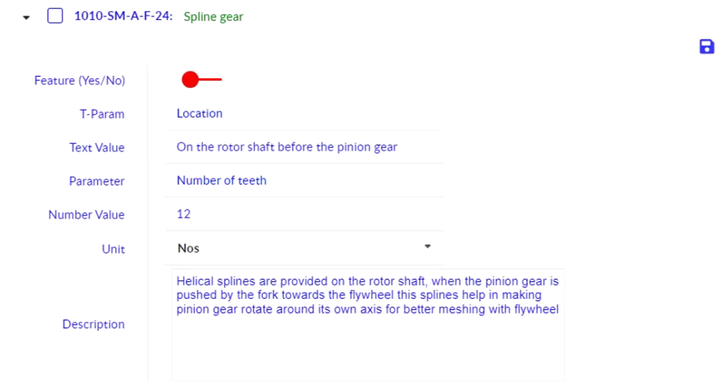
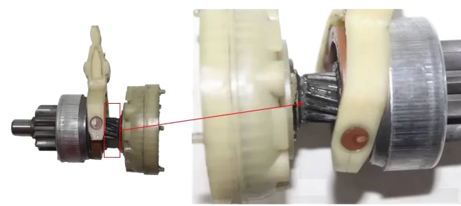
3. Spline Gear
Longitudinal and rotational motion is observed while the pinion gear moves along the shaft, made possible by the spline gear on the planetary carrier output shaft. This also helps in better meshing of the pinion gear with the flywheel.
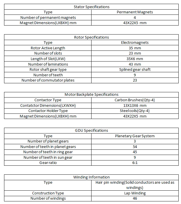
04Technical Specifications
Specifications are categorised into product level and part level. The product-level specifications capture the overall system parameters while part-level specifications detail individual component characteristics.
Product-Level Specifications

Part-Level Specifications
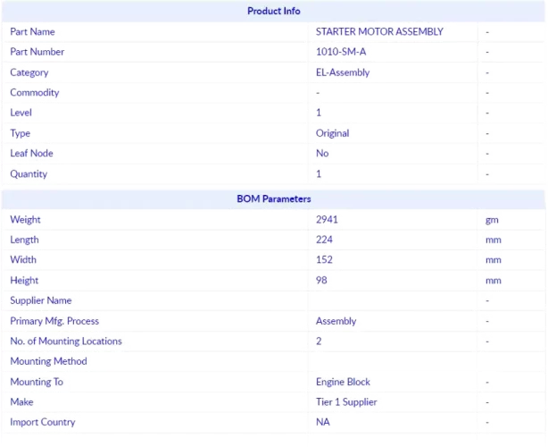
05BOM Study (xcPEP)
Product-Level BOM
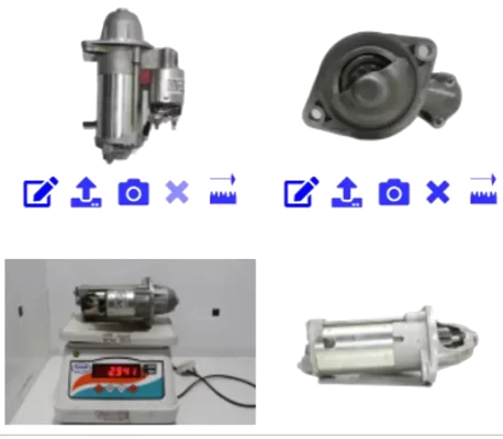
A product level BOM is first created on xcPEP which outlines the basic data of the product as an entity. The details mapped include weight, box dimensions, supplier data, mounting method and mounting locations. Orthographic and isometric views of the part and any information present on the part (information stickers) are captured and updated.
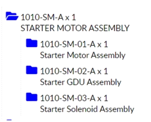
BOM Hierarchy & Part Mapping
Once the product level data entry is done, the product is torn down into different sub-assemblies or sub-systems based on functionality. The subsystem list is represented in a hierarchical structure. After mapping all product data, the product is further divided into sub-systems for which the same data are also mapped.
The sub-systems are further torn down to last level, and all individual parts are created under their respective sub-systems. Each part is mapped with box dimensions, materials, surface coating and thickness, supplier data, manufacturing processes (primary, secondary, and tertiary), and dependencies.
06Architecture & Layout
Product level architecture is categorised into packaging diagrams and interface diagrams, providing a complete understanding of how the starter motor is assembled and how its components interact.
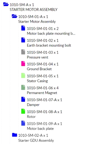
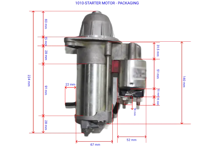
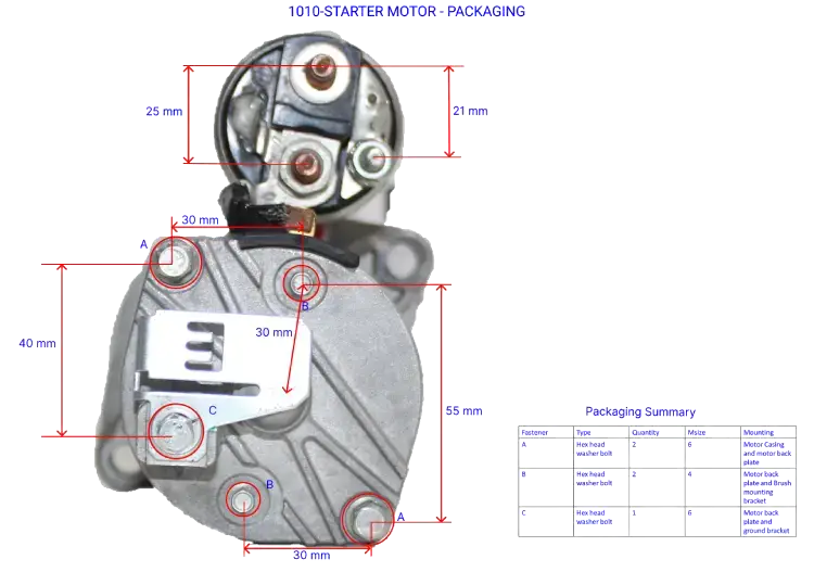
Packaging Diagram
All the major dimensions required to design a part are given under the packaging diagram. Dimensions in all orthographic views are marked, and a summary table provides fastener details such as type, M-size, and mounting locations.
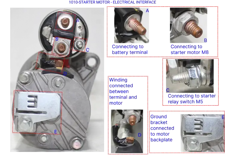
Interface Diagram
The interface diagram consists of all details regarding the interface between parts. The electrical interface diagram covers all electrical connections including connector details, male and female connectors, and fastener details.
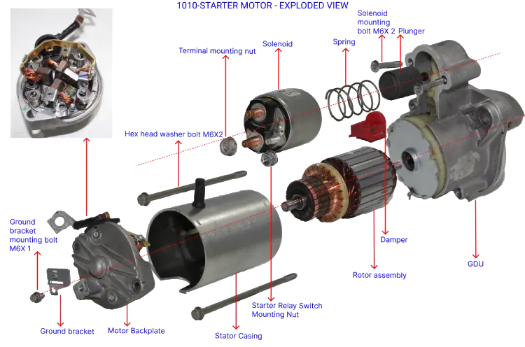
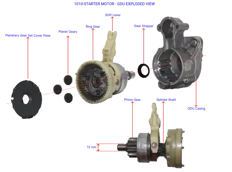
Exploded Views
The exploded view illustrates the series in which parts are mounted to each other. The GDU (Gear Drive Unit) contains a planetary gear set used for torque multiplication, consisting of three planetary gears, a ring gear, and a sun gear.
Input is given to the sun gear which rotates the planet gears guided by the ring gear. The starter motor transmits power to the pinion gear through the planetary carrier, which then transmits power to the flywheel. For one rotation of the planetary carrier, the sun gear has to rotate six times.
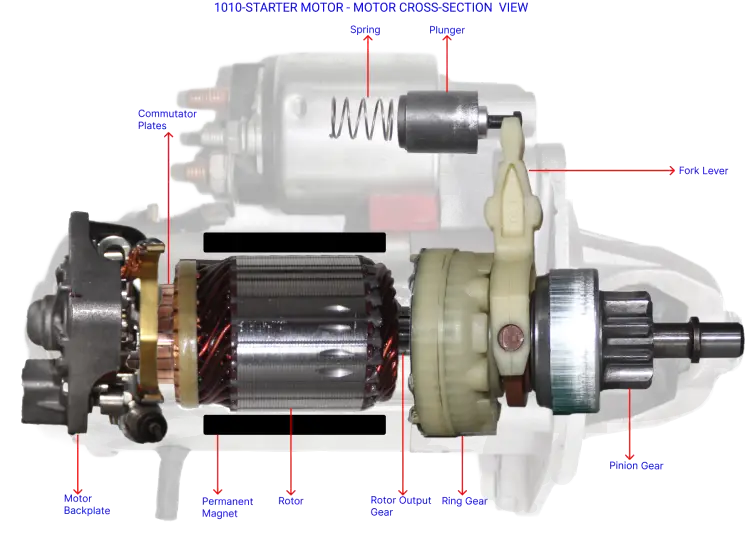
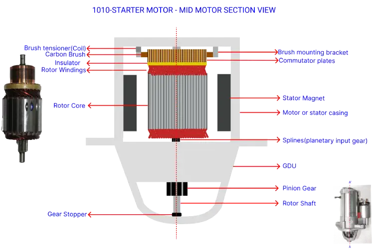
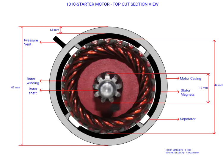
Cut Section Views
Cut section views are used to understand the interior connections of individual parts present inside the motor.
Software Platforms Used
Should Cost Software
xcPEP delivers real-world accurate, transparent and defensible should cost analysis of mechanical, electrical and electronics components from drawings or physical parts.
Explore xcPEP →Should CostData
xcPROC is the centralized database engine powering xcPEP. Each database is meticulously curated by a dedicated data research team to be region-specific and time-specific.
Explore xcPROC →