Refrigerator Compressor Should Costing & Benchmarking: BOM, Cost Drivers and Procurement Insights
Disclaimer
This study was conducted entirely in-house by ASI Engineering to demonstrate the capabilities of the xcPEP® platform. The product was independently procured by ASI. No proprietary or confidential information from any other party has been used. Results are not updated after publishing.
Software platforms used for this study
This study is powered by ASI’s proprietary should-costing ecosystem - xcPEP and xcPROC - engineered to deliver real-world accurate, traceable should-costing across mechanical, electrical, and electronics components..

xcPEP delivers real-world accurate, transparent & defensible should cost analysis of mechanical, electrical & electronics components from drawings or physical parts.
Explore xcPEP →
xcPROC is the centralized database engine powering xcPEP. Built entirely by ASI’s data research team, each database is meticulously curated to be region-specific and time-specific.
Explore xcPROC →Introduction: Decoding Refrigerator Compressor Costs through Should Costing & Component Benchmarking
The home appliance industry in India is witnessing steady growth, driven by increasing consumer demand for energy-efficient and affordable refrigeration solutions. As manufacturers
focus on improving performance and adhering to energy ratings, understanding the cost dynamics of key components—especially the refrigerator compressor—becomes crucial for pricing, sourcing, and design decisions.
This analysis dives deep into the teardown and should-costing evaluation of a typical single-door refrigerator compressor, used in a popular 190L, 2-star rated model. We explore the Bill of Materials (BOM) in detail and map out the cost contribution of compressor subcomponents, such as the rotor, stator, enclosure, and refrigerant-related fittings. This comprehensive study aims to deliver insights into compressor cost optimization, energy efficiency enhancements, and supplier benchmarking to help OEMs and component manufacturers make informed engineering and procurement decisions.

Refrigerator Compressor Specifications: A Foundation for Cost Analysis
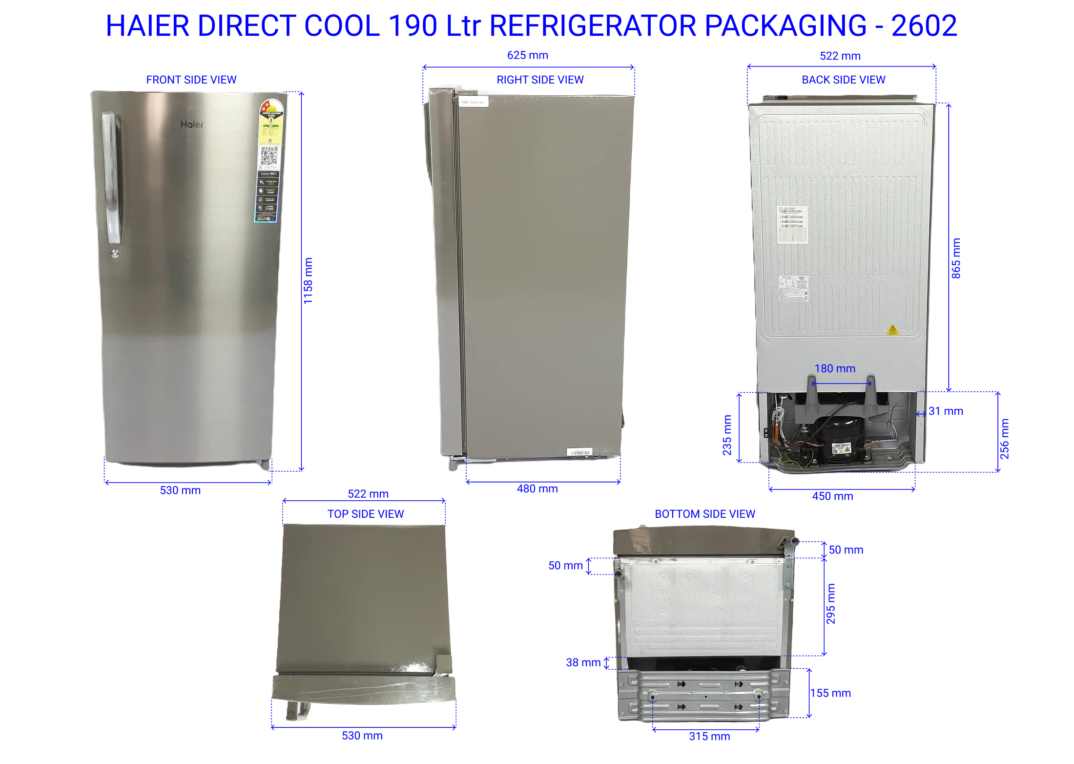
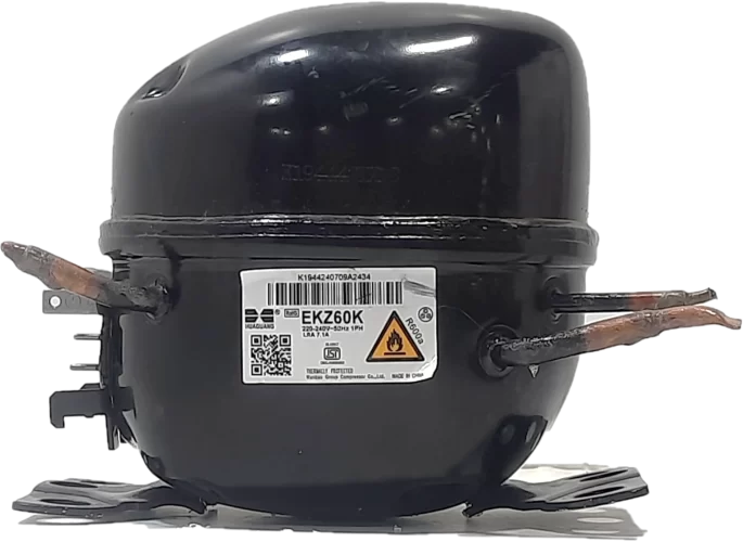
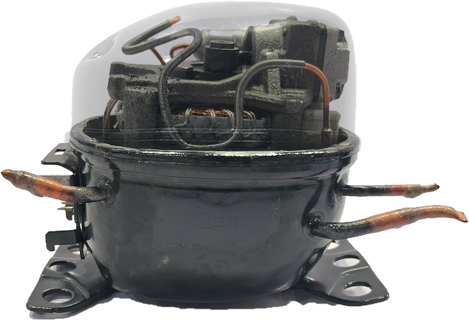
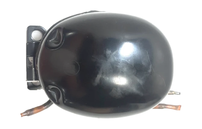
Understanding component-level specifications is essential for accurate cost estimations and engineering analysis. In this case, we examine the refrigerator compressor used in the Haier 190 L, 2-Star, Direct Cool Single Door Refrigerator (Model: HRD-2102BNS-P). As a commonly used appliance in the Indian household segment, this model provides a relevant basis for compressor should-cost evaluation.
Parameter
Details
Compressor Component Architecture: Deconstructing for Cost Insights
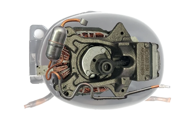
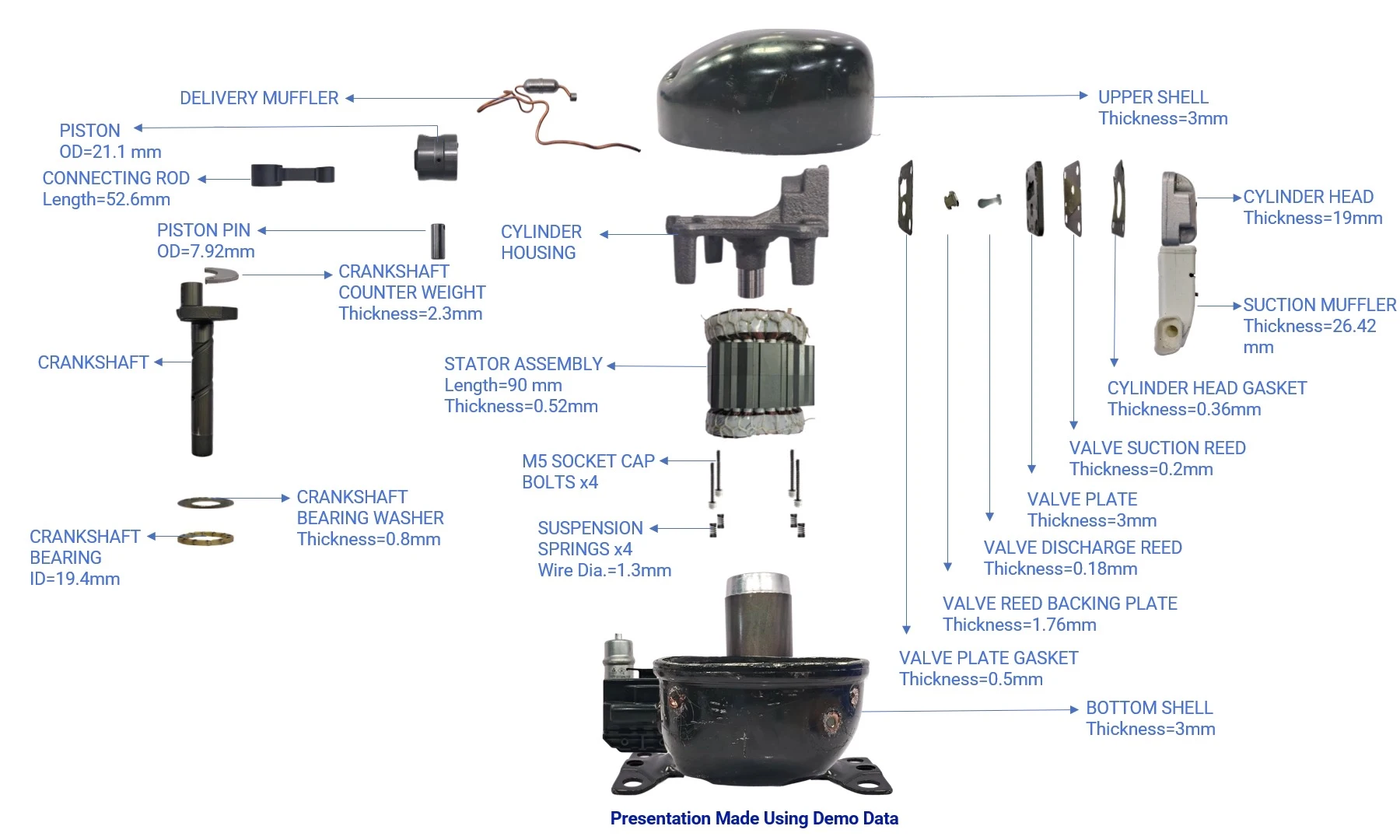
The refrigerator compressor may appear compact, but it comprises several intricately engineered components working in unison to deliver efficient refrigerant compression. A
detailed teardown of the compressor helps us understand assembly complexity, component interdependence, and key cost-driving elements—critical to precise should costing and appliance benchmarking.
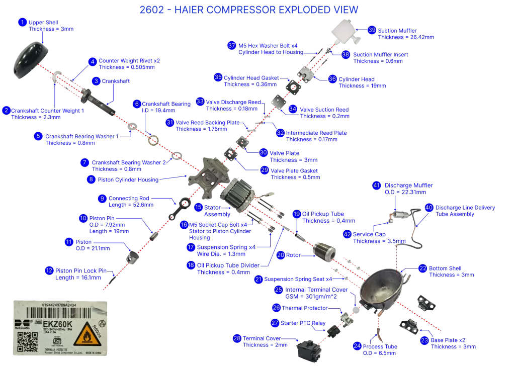
This compressor component breakdown allows us to identify material choices, manufacturing intricacies, and integration challenges, offering a structured view into refrigerator compressor cost drivers. Below are the primary elements analysed during teardown:
Electric Motor Assembly: Powering the Compression Cycle
At the heart of the compressor lies the electric motor, which converts electrical energy into mechanical motion. It includes copper windings, stator laminations, and a dynamically balanced rotor shaft. These subcomponents contribute significantly to the electromagnetic performance and cost structure of the compressor.
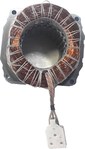
Motor Stator
Weight: 1984 g
Material: Copper and steel(CRNGO)
Function: Generates the magnetic field to drive the
rotor.
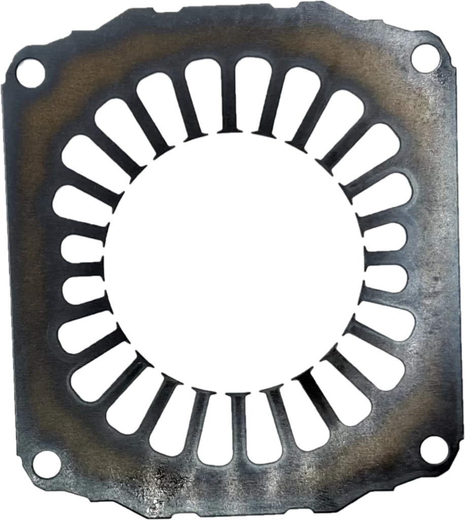
Stator Core
Weight: 17 g | Quantity: 78 nos
Material: Electrical Steel (CRNGO)
Function: Provides a magnetic path and supports stator windings.
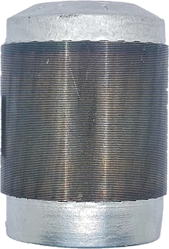
Motor Rotor
Weight: 594 g
Material: Aluminium & Steel
Function: Spins inside the stator to create mechanical energy
Crankshaft: Translating Motion
The steel crankshaft converts the rotary action of the motor into the reciprocating motion required to drive the piston. Precision machining and material selection here are essential for durability and low friction losses, directly influencing the mechanical efficiency and part cost.
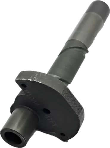
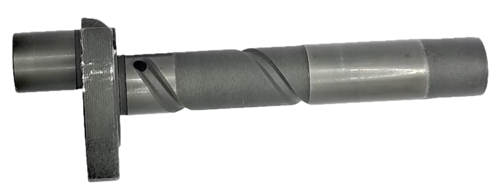
Crankshaft
Weight: 118 g
Material: SAE 4140
Function: Drives the piston in the cylinder block
Piston and Cylinder Assembly: Compression Core
This subsystem is responsible for compressing the refrigerant gas. Made of hardened steel or cast iron, the piston-cylinder pair is subject to high-pressure loads and must maintain tight tolerances. Their weight and finish contribute measurably to the compression efficiency and material cost.
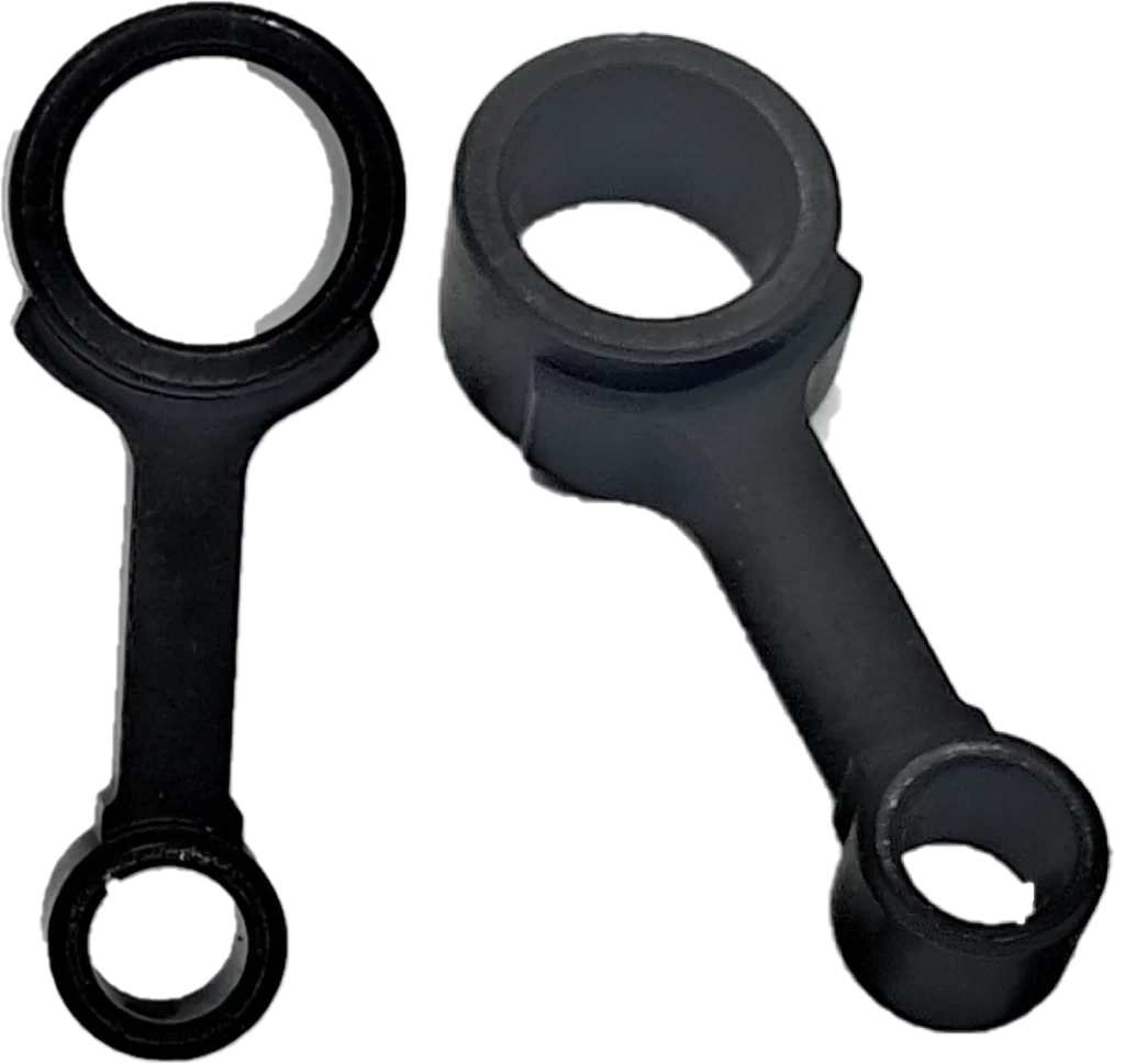
Connecting Rod
Weight: 22 g
Material: Fe-Cu powder (Iron-copper powder)
Commodity: Powder metallurgy.
Function: Transfers crankshaft motion to the piston.
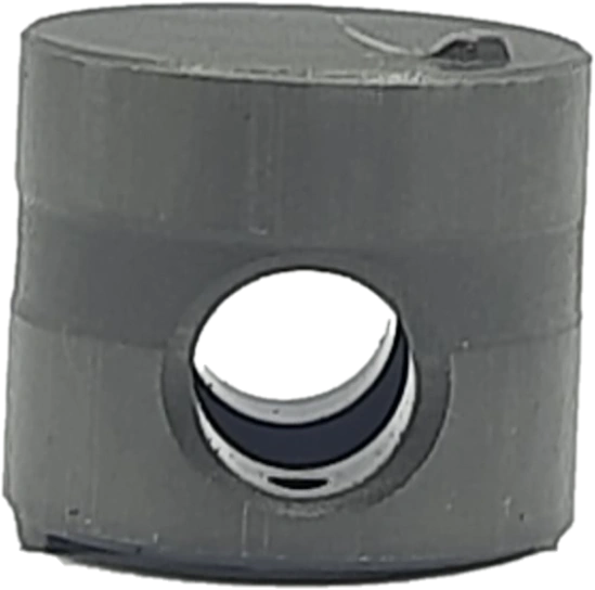
Piston
Weight: 20 g
Material: Fe-Cu powder (Iron-copper powder)
Commodity: Powder metallurgy
Function: Compresses refrigerant gas.
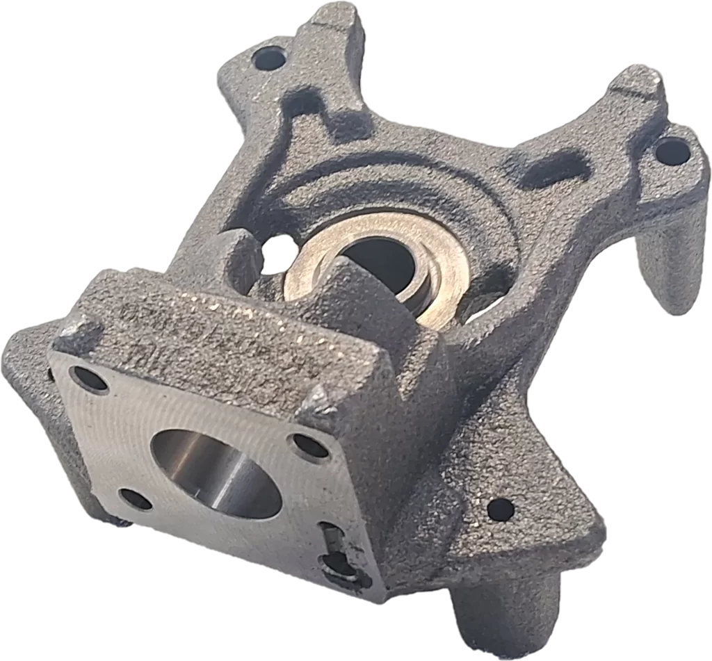
Piston Cylinder Housing
Weight: 904 g
Material: cast iron
Commodity: Sand Casting
Function: Encloses piston; forms chamber for compression.
Valve Plate & Reed Valves: Gas Flow Control
A critical component set includes reed valves made of stainless steel and the valve plate, which together manage refrigerant intake and discharge. These thin precision-formed parts ensure unidirectional gas flow and must withstand repeated thermal cycles without fatigue, key contributors to functional performance and cost.
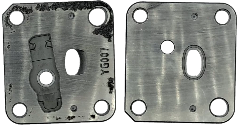
Valve Plate
Weight: 34 g
Material: Fe-Cu powder (Iron-copper powder)
Commodity: Powder metallurgy
Function: Holds and supports suction and discharge reeds.
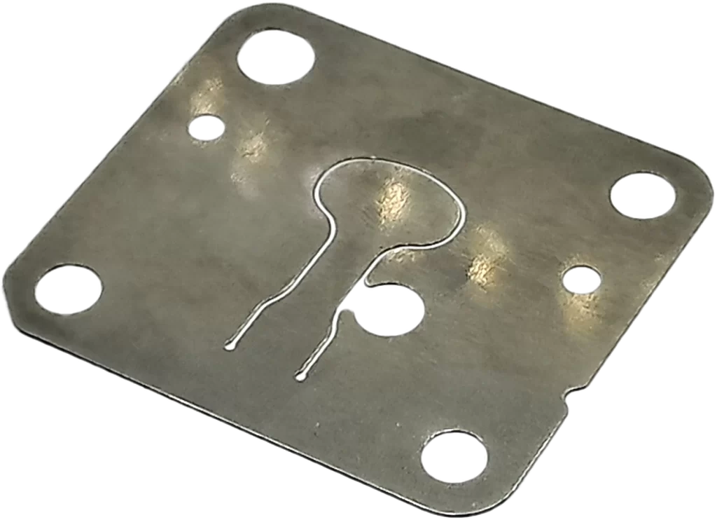
Valve Suction Reed
Weight: 2 g
Material: Steel
Function: Opens to allow refrigerant into cylinder.
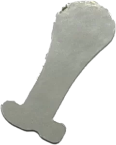
Valve Discharge Reed
Weight: 0.15 g
Material: Steel
Function: Opens to release compressed refrigerant gas.
Compressor Shell: Structural Housing
The outer casing, typically deep-drawn or welded steel, acts as a pressure vessel and vibration damper. It provides mechanical protection, thermal insulation, and oil retention, all while ensuring leak-proof operation. The shell’s size, material thickness, and weld quality contribute significantly to the structural integrity and overall unit cost.
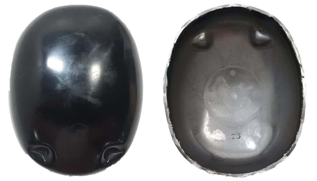
Upper Shell
Weight: 681 g
Material: Steel
Commodity: Sheet metal fabrication
Function: Covers motor and discharge components; ensures sealing.
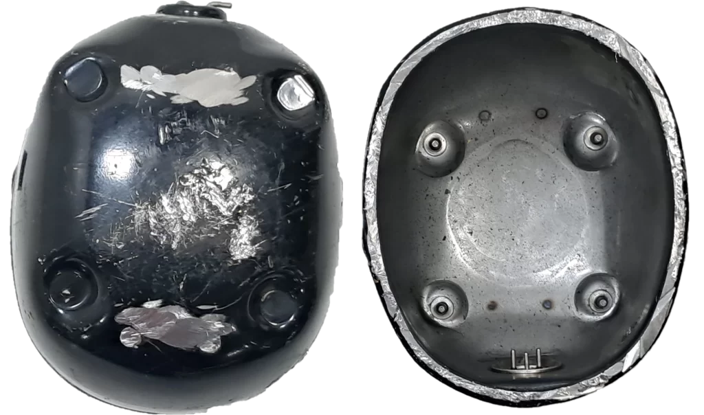
Lower Shell
Weight: 1226 g
Material: Steel
Commodity: Sheet metal fabrication
Function: Houses motor and crank;
supports compressor base.
Functioning of Compressor: Understanding Suction and Compression Cycle
The compressor serves as the central component of the refrigeration system, ensuring continuous circulation of refrigerant throughout the cooling cycle. In a Haier compressor, this operation occurs in two distinct stages — suction and compression — each illustrated in the diagrams provided.
Suction Stage
In the suction phase, the single-phase induction motor (230 V, 50 Hz) rotates the crankshaft, which transfers motion through the connecting rod to drive the piston downward inside the cylinder housing. This increases the internal chamber volume and creates a low-pressure zone, causing the valve suction reed to lift. Low-pressure R600a refrigerant from the evaporator is then drawn into the cylinder through the suction muffler, which reduces intake noise and vibration. Lubricating oil in the crankcase coats the moving parts, ensuring smooth operation and minimizing wear — factors that can impact service life and maintenance costs.
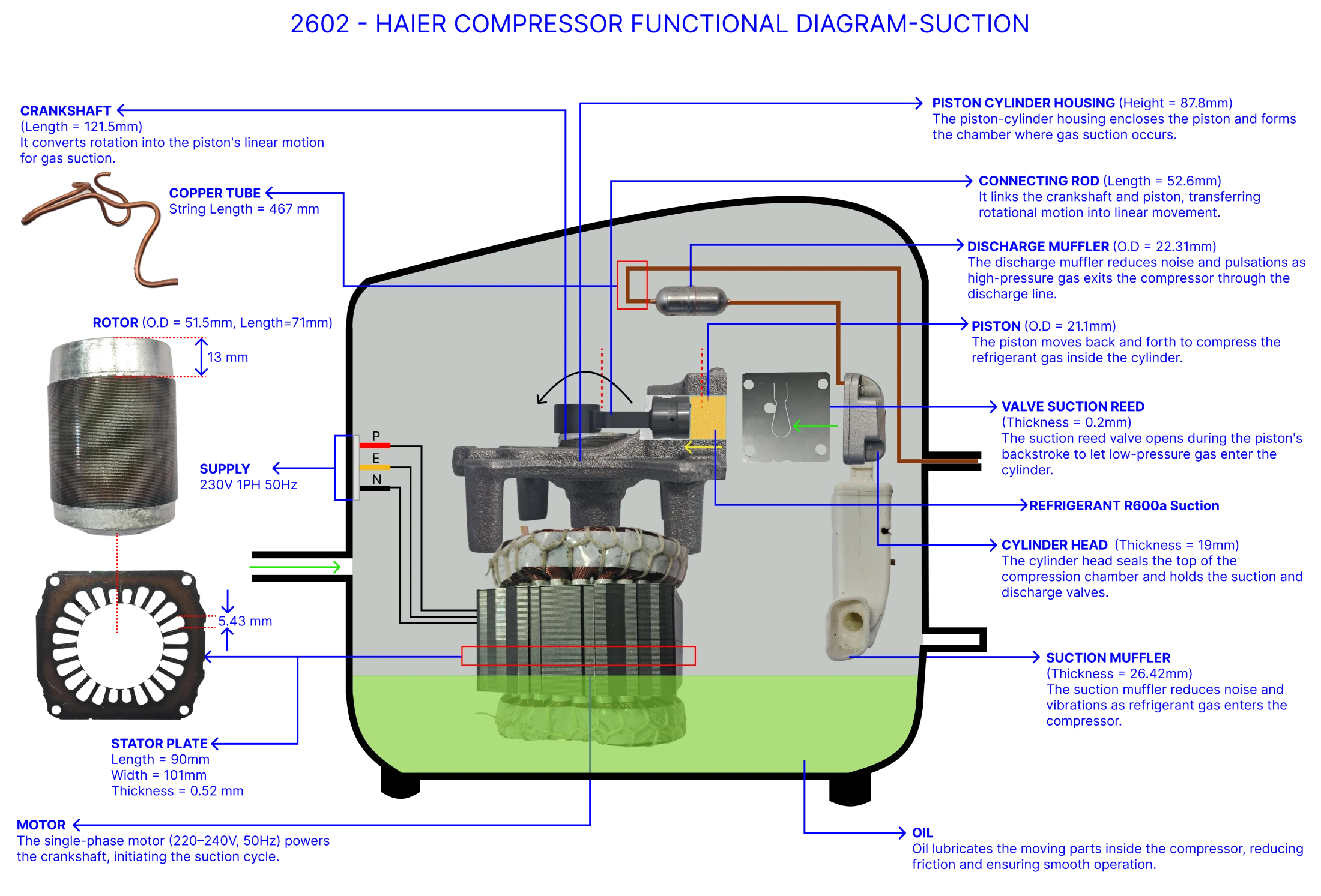
Suction Stage
Compression Stage
As the crankshaft continues its rotation, the piston moves upward, reducing the chamber volume and compressing the refrigerant gas. The valve suction reed closes to prevent reverse flow, and pressure builds rapidly. Once the internal pressure exceeds the discharge pressure, the valve discharge reed opens, allowing the high-pressure, high-temperature refrigerant to pass through the discharge muffler before flowing to the condenser. The precision and durability of these valve components are critical, as they influence efficiency, noise levels, and the cost competitiveness of the design.
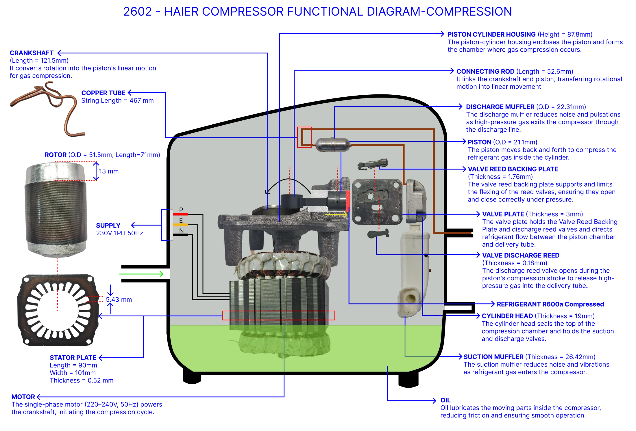
Compression Stage
Bill of Materials (BOM)
Part Name
Material
Weight (g)
Function
Compressor BOM Weight Distribution Analysis
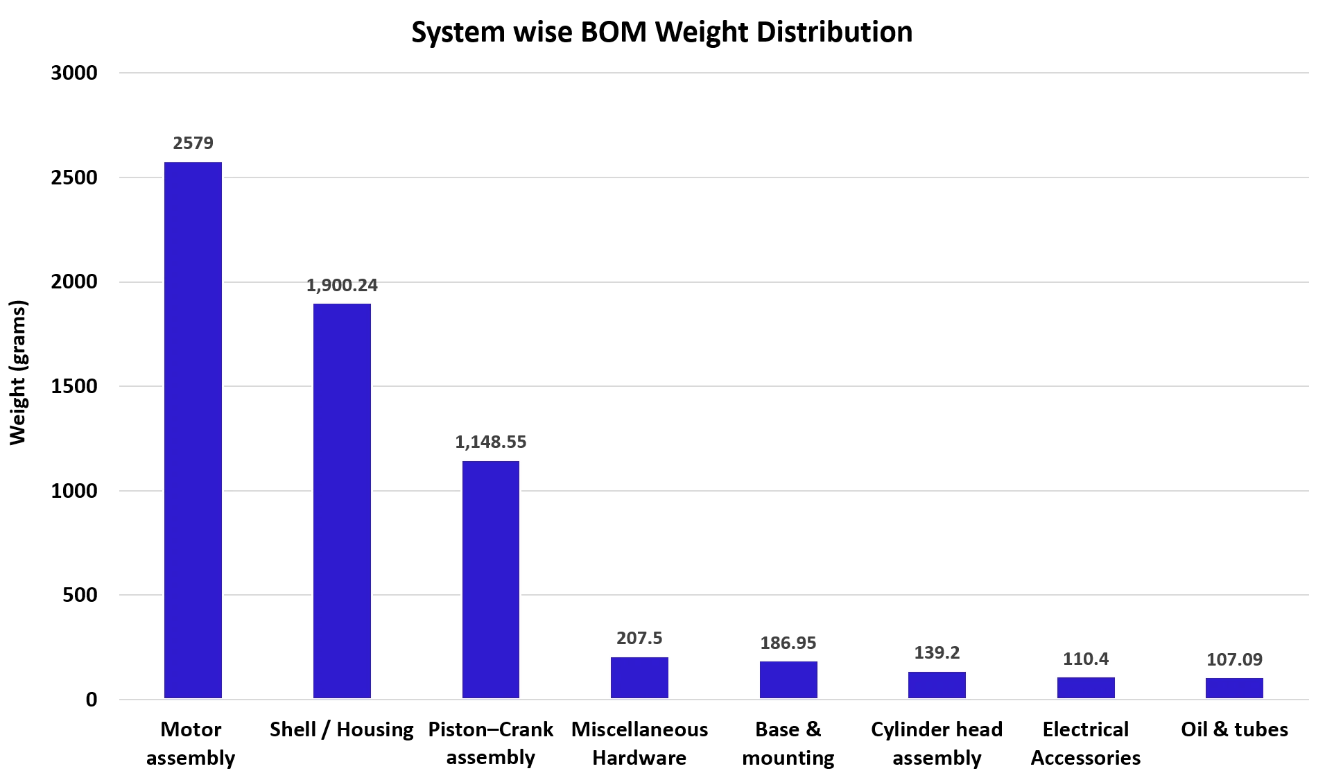
A key step in compressor benchmarking and should-cost analysis is understanding how weight is distributed across subassemblies. Since material cost often scales with weight, the BOM weight distribution highlights major cost drivers.
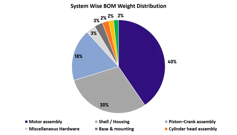
For the hermetic reciprocating compressor analyzed, the total weight is 6,378 grams (before teardown). The weight breakdown is shown in the pie chart below:
- Motor Assembly (40.4%) – Stator and rotor with copper windings and steel cores; largest cost and weight contributor.
- Shell / Housing (29.8%) – Upper and lower steel shells; provide structural strength and hermetic seal.
- Piston–Crank Assembly (18.0%) – Includes piston, crankshaft, connecting rod, and bearings; key for compression reliability.
- Cylinder Head Assembly (2.2%) – Suction/discharge valves and mufflers; small weight but critical for efficiency and noise.
- Base & Mounting (2.9%) – Base plate and mounts for vibration damping and stability.
- Oil & Tubes (1.7%) – Lubricating oil and refrigerant tubing for smooth operation.
- Electrical Accessories (1.7%) – Relays, capacitors, and thermal protectors; lightweight but essential for motor start-up.
- Miscellaneous Hardware (3.3%) – Bolts, washers, springs, and minor fittings.
Manufacturing Category Distribution Analysis
From the analysis:
- Fabrication – Sheet Metal (P) (45.9%) and Mechanical Bought-Out Part (BOP) (43.9%): Account for the majority of parts, reflecting the extensive use of sheet metal components
and mechanical assemblies in the compressor. - Bought-Out Parts (BOP) (1.5%), Stator Assembly (0.5%), and Wiring Harnesses (1.5% combined): Fewer in number but represent specialized and critical components.
- Cold Forging (2.0%), Hot Forging (0.5%), Powder Metallurgy (1.0%), and Fe Casting (0.5%): Minimal part counts yet vital for durability and mechanical integrity.
- Consumables and small fittings including bolts and hard consumables (1.0% combined): Contribute to assembly stability and ensure proper functioning of the compressor.

The analysis shows that nearly 90% of the parts are from fabricated sheet metal and mechanical bought-out categories, highlighting the strong reliance on metal forming processes in compressor design.
Detailed Should Costing Analysis of Compressor
The compressor was analyzed to estimate its manufacturing cost using a detailed should-costing approach. The study considered factors such as material costs, labor, production volumes, and component sourcing. Key insights from the analysis are summarized below:
- The compressor was manufactured in India.
- The estimated production volume used for the study was 40,000 units annually.
- The latest material rates and labor cost benchmarks were referenced for Q1 FY25-26.
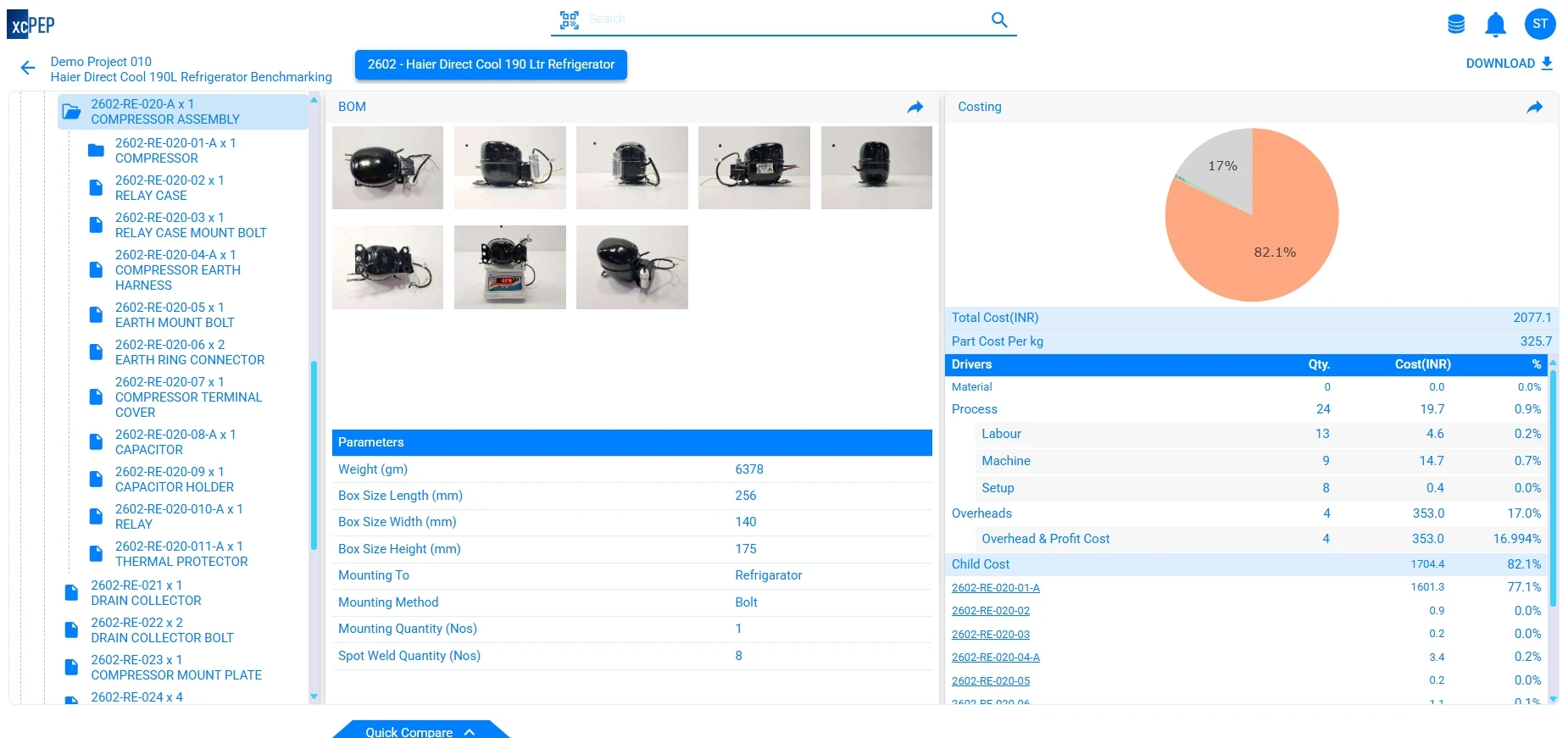
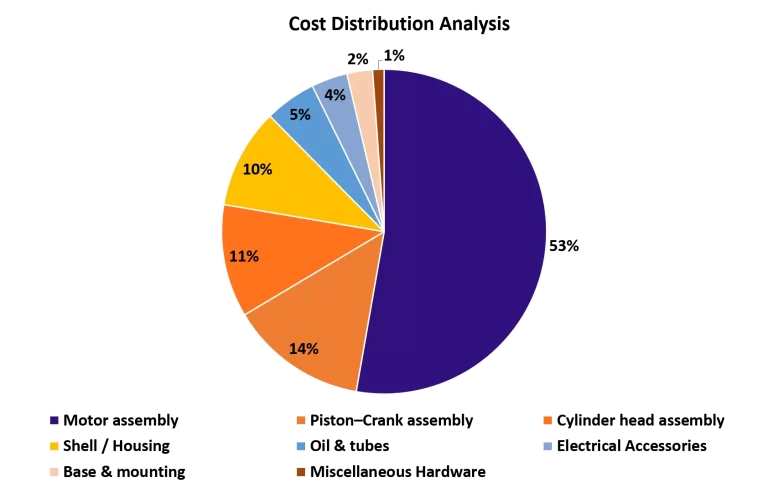
The total calculated cost of the compressor is ₹2077.09, with the Motor Assembly contributing the largest share.
Weight vs Cost Correlation
- Motor Assembly – The heaviest subassembly (40.4% of weight) also accounts for the highest share of cost (~71%), confirming its role as the dominant cost driver.
- Shell / Housing – Although it contributes nearly 30% of total weight, its cost share is only ~13%, indicating relatively lower material and processing cost per unit weight.
- Piston–Crank Assembly – At 18% of weight and 12% of cost, this subassembly shows balanced weight-to-cost contribution, reflecting efficiency in material usage.
- Electrical Accessories & Oil/Tubes – Despite contributing less than 2% each to total weight, they account for 4–5% of cost, highlighting that certain lightweight parts can carry disproportionately high costs.
- Miscellaneous Hardware – With 3.3% weight but less than 1% of cost, this category demonstrates minimal cost impact despite its presence in the BOM.
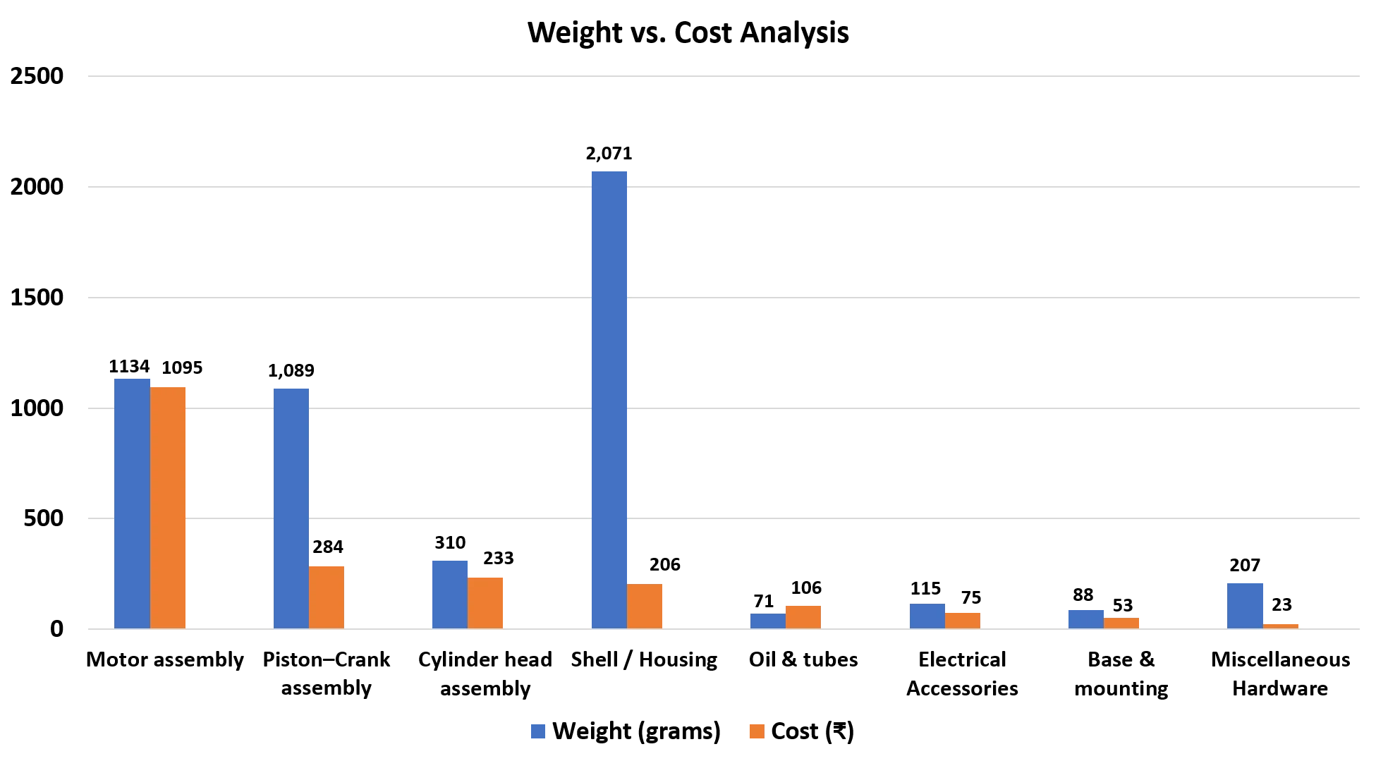
While heavier assemblies such as the motor and shell dominate overall cost and weight, lightweight parts like electrical accessories can also become significant cost contributors, underscoring the importance of analyzing both weight and cost distributions together.
Should-Cost Analysis
A comprehensive should-cost estimation considers regional production volumes,
manufacturing methods, and material prices. Based on our benchmarking for a compressor model weighing ~6.378 kg, the cost analysis is as follows:
- Raw Material Cost: ₹995.16 (~47.9%)
- Bought out parts : ₹258.79 (~12.5%)
- Process cost : ₹396.1 (~19.1%)
- Overheads: ₹427.1 (~20.6%)
📌 Estimated Should-Cost: ₹2077.15 per unit (India, 40k units/year)
Insights Gained from the Teardown
– Copper windings form a major portion of cost and weight (~14% of total cost).
– The sealed structure and precise machining of the crankshaft and cylinder block make machining a significant cost contributor.
– Insulation, gaskets, and plastic inserts—though low in weight—are critical to long-term performance.
– Local sourcing of sub-assemblies (motor windings, valve plates) can reduce cost by up to 10%.
– Minimal space inside shell implies tight tolerances, leading to increased setup and process control requirements.
Summary Table: BOM and Should-Cost Overview
- Production Volume Considered: 40,000 units/year (India)
- Total Assembly Weight: ~6.378 kilograms
- Estimated Should-Cost (India): ₹2077.15 per unit
- Major Cost Driver: Stator assembly and Copper windings
Conclusion
This refrigerator compressor teardown provides deep insight into component-level cost contributors and optimization opportunities. Through BOM and should-cost benchmarking, OEMs and procurement teams can identify areas for cost rationalization, supplier localization, and design simplification.
Whether you’re an engineer, buyer, or product manager, such insights can support smarter sourcing and more competitive product development.

